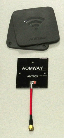
Aomway Patch ANT005
A patch antenna with very dubious specs. They claim that this thing is circularly polarized, but it actually looks like it consists of a 2x2 array of linearly polarized patches, which makes no sense. RCModelReviews also said that the performance of this thing was disappointing. There are also plenty of things about the design that don't make sense. To quote my own comment to the RCModelReviews video:
Bruce, I think I can explain why this thing doesn't work well. I'm an EE PhD student and I have some experience with this stuff. Based on this video alone I already see a lot of problems with the design:
- Like others have said, if this really was a circularly polarized antenna, the patches would need to have two feedpoints, or some kind of asymmetry (slots, vias, ...) to turn linear polarization into circular polarization. I don't see any of that, so I assume that this is just a vertically polarized antenna.
- You are right, FR4 is a bad choice for this type of antenna, the loss will be very high.
- If this antenna works at all, it will have an extremely narrow bandwidth, because the spacing between the patches and the ground plane is way too small. This is made worse by the fact that they used a high-DK material (FR4). Note how your other antenna has a bigger spacing and uses foam (which has a very low DK, almost like air) to avoid this problem. I would guess that the bandwidth of this thing is 50-100MHz, which doesn't even cover the full 5.8GHz band.
- Because of the extremely narrow bandwidth the design is extremely sensitive to manufacturing variations (because these shift the center frequency of the antenna away from 5.8GHz). A big problem here is that cheap FR4 has a highly variable dielectric constant (DK), so two antennas from a different batch could have a significantly different center frequency. This design has maybe 1% tolerance for manufacturing variations based on the bandwidth. This would be less of an issue if they used a high-quality RF material, but these are far more expensive, and even then it's pretty optimistic to expect less than 1% manufacturing tolerances.
- The lack of phase shift between the left and right patches is not an error, this is actually correct. All patches should have the same phase so the radiation adds up. The required phase shift just depends on the position of the feedpoint. The bottom needs 180 degrees phase shift relative to the top, which explains the weird shape of those microstrips. What is missing here is the left/right feedpoints which would need 90/270 degrees phase shift.
- The design seems to rely very heavily on filters/matching structures. This is one of those things that works great in theory but not in practice. The EM simulators used to design these antennas are notoriously inaccurate, it's common to see errors up to 5% even when you're careful. That's 5% for each component. As the number of components in the design goes up, so does the total error. Then there's manufacturing tolerances. In a complex design like this, the real-world performance can be completely different from the simulated performance. This is why a good designer will try to keep everything as simple as possible.
- That large metal patch near the coax is very fishy. Same for the big copper soldering pad. At 5.8GHz such a structure is basically a giant capacitor. Presumably they added this to match the antenna to the 50 ohm coax, but if the rest of the circuit had been properly designed then this wouldn't even be necessary. This again increases sensitivity to manufacturing tolerances and simulator inaccuracies. Everything combined, it seems like the designer didn't really know what he was doing and designed this thing through trial-and-error, while blindly trusting the simulator. It would be interesting to connect this thing to a network analyzer to see the return loss (s11) - maybe it actually works fine at a completely different frequency.
My measurements confirm that this thing has some serious flaws. I didn't get a chance to do anechoic chamber measurements of this thing, but I suspect that the radiation pattern wouldn't look anything like what it is supposed to be.
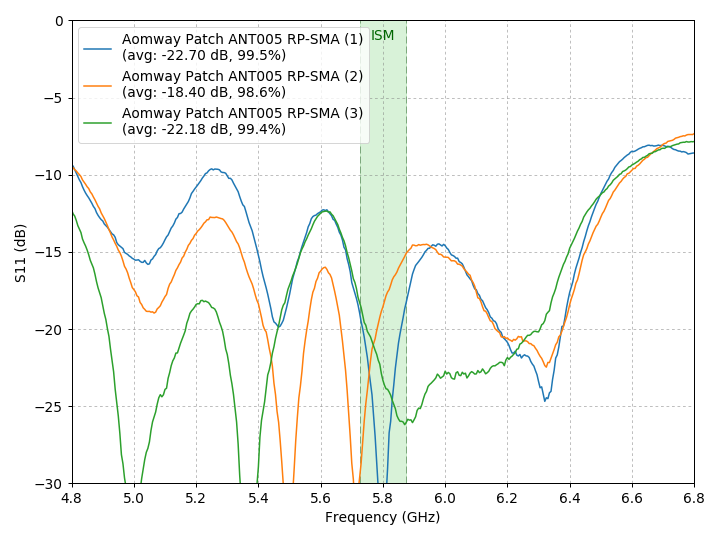
VNA measurements
|
|
Matching may appear okay at first sight, but I immediately noticed that the graph changes completely simply depending on where I'm holding the coax cable. The three graphs show the exact same unit, the only difference is that I've changed the place where I'm holding the coax. The antenna is in the same location and orientation in all three measurements. My hand wasn't anywhere close to the antenna, so this really should not happen. It suggests that the majority of the energy isn't radiated but actually couples with the outside of the coax cable. So the cable is acting as the antenna, not the patch itself. |
Comments
Michiganbroadband |
Comment #1: Fri, 30 Aug 2019, 18:27 (GMT+1, DST) And all of this said and tested. |