MB Pagoda-2
My own Pagoda antenna, more information here.
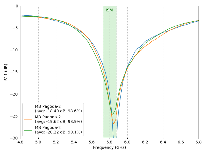
VNA measurements
|
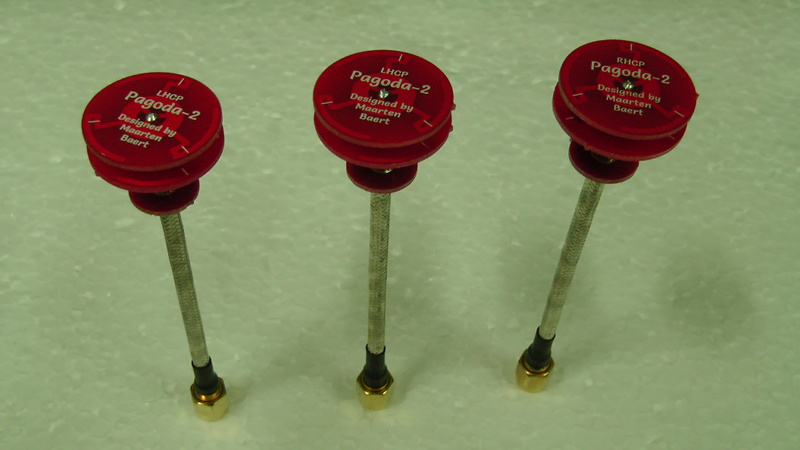
Prototype units used for measurements, two LHCP and one RHCP. |
Three different units with slightly different coax lengths. They all have very good matching. The center frequency is slightly higher than 5.8 GHz though. |
Anechoic chamber measurements
|
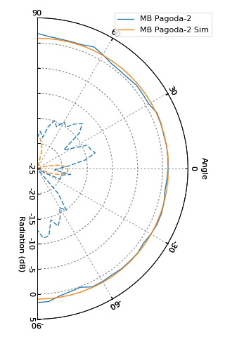
Horizontal radiation pattern. The antenna is completely omnidirectional in this plane and the axial ratio is very good. The radiation pattern matches well with simulation results, although the real-world axial ratio is not as perfect as the simulation. |
|
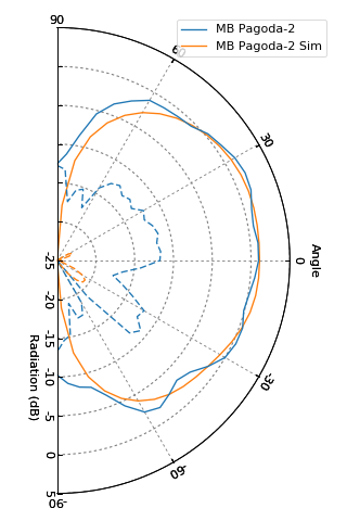
Vertical radiation pattern. You can see the nulls at the top and bottom. There is some ripple compared to the simulation results, which is similar to what simulations predict when you actually include the coax in the simulation. The reduced axial ratio compared to simulation is likely also a result of radiation from the coax, combined with imperfections of the anechoic chamber. |
|
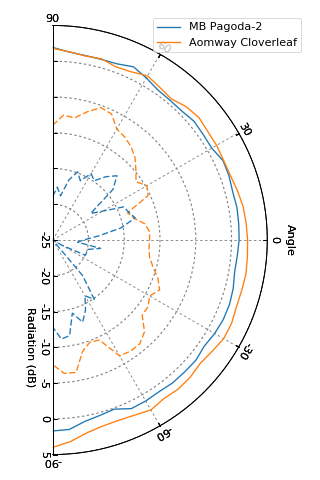
For comparison, the Pagoda-2 still has a much better axial ratio than a typical cloverleaf, such as this one from Aomway. The antenna gain is slightly lower though, which could be the result of higher losses in the FR4, or it could just mean that the radiation pattern of the cloverleaf is more flattened out. I have not done a vertical measurement to confirm this. |
Comments
There are no comments yet.