Directivity
Some antennas are designed to be omnidirectional, which means that they emit an equally strong signal in all directions. Dipole and cloverleaf antennas are the most common examples. Others are designed to emit their signal in only one specific direction. Popular examples are Yagi-Uda antennas, patch antennas and helical antennas. Both types have advantages and disadvantages, and which one will perform best depends on the application. FPV transmitters almost always use omnidirectional antennas since the orientation of the RC model changes constantly. FPV receivers can also use omnidirectional antennas, but directional antennas can provide better range as long as they are aimed at the transmitter. It's also possible to use a diversity receiver connected to one omnidirectional antenna and one directional antenna. This approach gives you the best of both worlds.
Radiation pattern
An omnidirectional antenna doesn't actually radiate in all directions, in fact this is mathematically impossible. Omnidirectional antennas have 'nulls', i.e. specific directions that don't get any signal at all. For most types there are two 'nulls', one 'null' is straight up and the other one is straight down. The radiation pattern of an antenna is often visualized as a 3D plot where the color and shape are proportional to the amount of power emitted in a certain direction. For example, this is what the radiation pattern of my Pagoda-2 antenna looks like:
|
3D radiation pattern of the Pagoda-2 antenna. |

While these 3D graphs look very nice, they can actually be quite misleading. When you see one of these, the first thing you should do is check the legend, because the range of the legend can change the appearance of the plot drastically. You should also check whether the legend is logarithmic (expressed in dB/dBi) or linear, because this completely changes the shape. Here are a few examples of the exact same radiation pattern, shown with a different legend:
|
Legend with 10dB range. |
Legend with 30dB range. |
Legend with 60dB range. |


If you want to actually see the numbers so you can compare two radiation patterns, it's usually better to look at cross-sections of the radiation pattern instead:
|
Best case, vertical cross-section taken at various angles. |
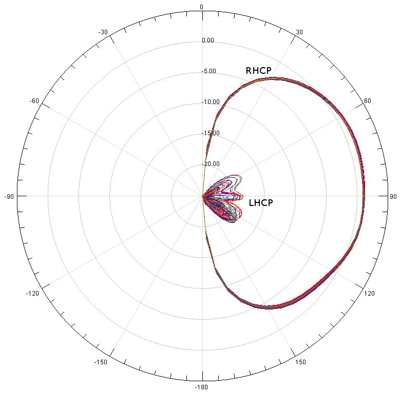
While this doesn't look quite as pretty, it contains exactly the same information, and it allows you to see the numbers far more accurately. Another advantage of cross-sections is that multiple polarization modes can be shown in one image.
Directivity, antenna gain, realized gain, ...
Radiation patterns describe the transmitted signal strength in various directions, usually expressed in dBi. 10 dBi corresponds to a relative power difference of a factor 10. The absolute power level will depend not only on the antenna but also on the output power of the transmitter. Radiation patterns do not take the transmitter output power into account, so what do these numbers actually mean? Unfortunately there isn't a single standard that everyone follows, so radiation patterns may display any of the following metrics:
-
Directivity: Radiation strength relative to a hypothetical perfectly isotropic radiator - a perfectly omnidirectional antenna. Such an antenna does not exist in reality, but we pretend that it does exist because it's a useful reference antenna for comparisons.
-
Antenna gain: The same as directivity, except that the antenna efficiency is also taken into account. A perfect antenna would have an efficiency of 100%, but in reality antennas are made out of imperfect materials: all conductors have some resistance, and all isolators absorb a small fraction of the electric field that passes through them. This results in energy loss, which reduces the actual transmitted power. For this reason, the antenna gain is always lower than the directivity.
-
Realized gain: The same as antenna gain, except that mismatch losses are also taken into account. If the antenna is not perfectly matched (usually to 50 Ohm), then some of the power from the transmitter won't be accepted by the antenna, and will instead be reflected back to the transmitter. This also results in energy loss, so the realized gain is always lower than the antenna gain.
The metric that actually matters in reality is realized gain, since it is the only metric that includes all losses that happen in the real world. This is why all my radiation patterns use realized gain, not antenna gain or directivity.
Conservation of energy
It is important to realize that an antenna can never create energy, it can only focus the existing energy in a narrower beam. In other words, the antenna gain can only be increased by also making the antenna more directional. High-gain antennas always have a narrower beam width. This is a direct consequence of conservation of energy.
Manufacturers will often specify the 'antenna gain' of their antenna as a single number, for example 2 dBi. They are talking about peak antenna gain (or in many cases peak directivity, since that number is slightly higher, and higher numbers sell better). The antenna will never achieve this gain in all possible directions.
An ideal omnidirectional antenna transmits the signal with the same signal strength in all directions. As a result it would have a directivity of 0 dBi. If there are no losses, then the antenna gain and realized gain are also 0 dBi. Real-world omnidirectional antennas are never truly omnidirectional since this is mathematically impossible. The lowest directivity you can typically get is around 1.5 dBi.
Some manufacturers claim to sell high-gain omnidirectional antennas. This is deceptive - high-gain antennas by definition cannot actually radiate equally in all directions. The term 'omnidirectional' usually means that the antenna achieves maximum signal strength only in the horizontal plane. If you mount these antennas vertically on a ground station, they will have higher gain near the horizon, but lower gain everywhere else. This can be useful if you are flying at low altitude and far away from your ground station, but if you are planning to fly at higher altitude above your own ground station, these antennas will actually perform much worse than a normal omnidirectional antenna with lower gain.
Reciprocity
The principle of reciprocity states that an antenna will behave the same for transmission and reception. This means that if an antenna has a high directivity, i.e. it focuses most of the transmitted energy in a specific direction, then the antenna will also be able to receive the strongest signal from that direction. In other words, the radiation patterns for transmitting and receiving are exactly the same. Antenna gain applies equally to the transmitter and the receiver.
Comments
There are no comments yet.