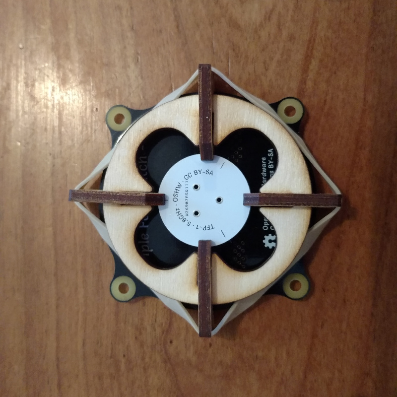
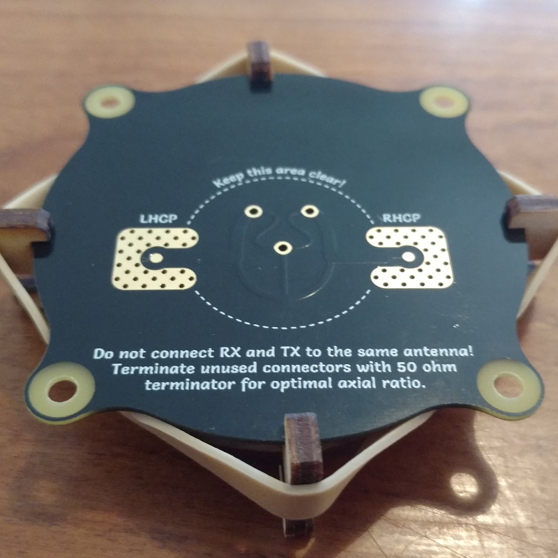
Triple Feed Patch antenna
The Triple Feed Patch antenna is a directional circularly polarized antenna that I created in collaboration with Robin Theunis, one of my co-workers. The main design goals were:
-
Good radiation efficiency. Most FR4-based patches have terrible efficiency because FR4 is very lossy at 5.8 GHz.
-
Good axial ratio, not just directly perpendicular to the patch but also off-center.
-
Cheap and easy to manufacture with high accuracy, even for a hobbyist.
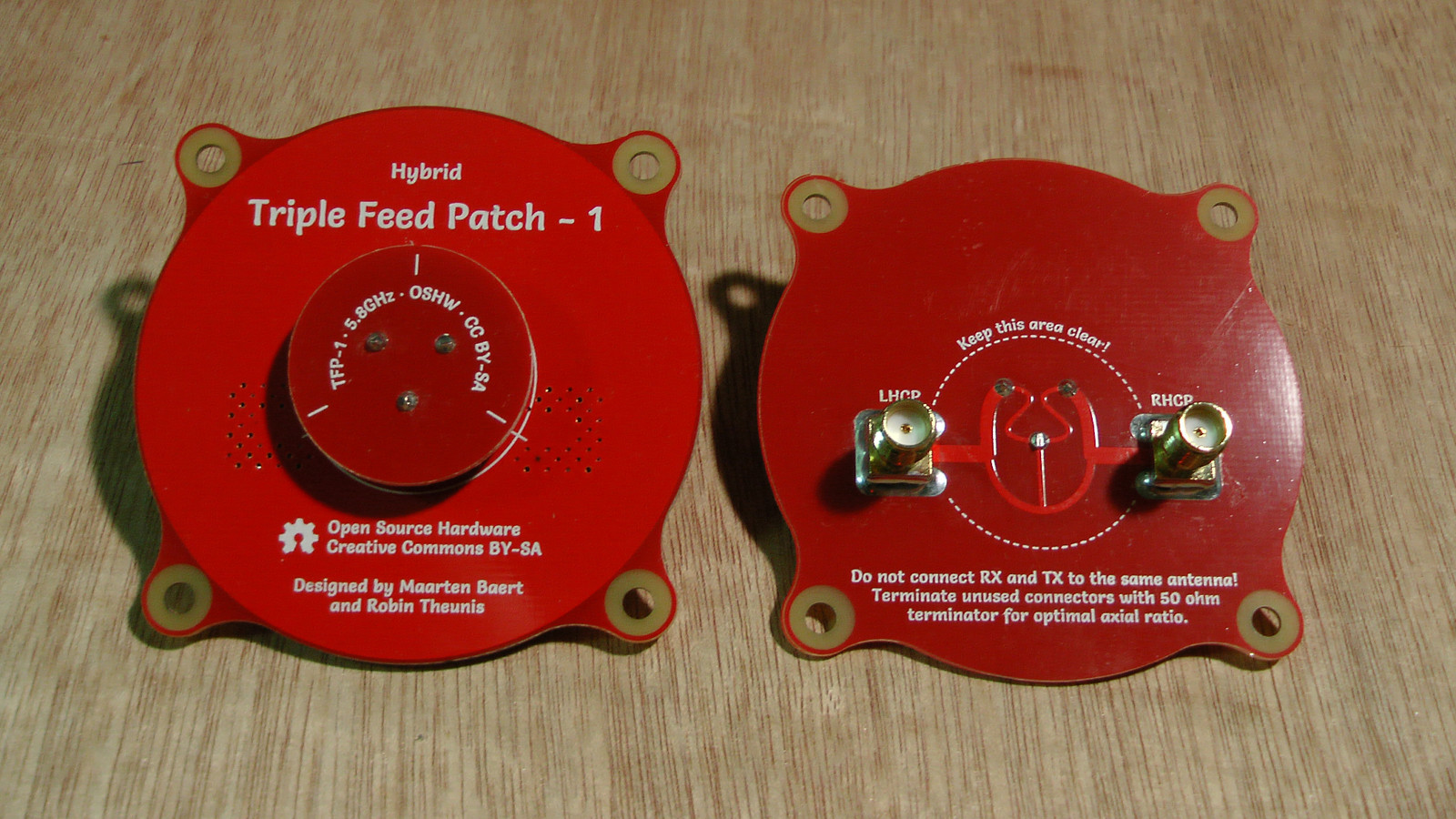
Photo of a Triple Feed Patch 1 prototype. This is the 'hybrid' variant, which is simultaneously LHCP and RHCP, with a different connector for each polarization. There is a regular single-connector LHCP/RHCP variant as well.
Special thanks to Antenna Test Lab who were kind enough to provide complete spherical anechoic chamber measurements (i.e. 3D radiation patterns) for the Triple Feed Patch antenna. You can find a detailed test report of the Triple Feed Patch antenna on their website.
Specifications
|
Simulated |
Measured |
Notes | |
|
Center frequency |
5.8 GHz |
5.8 GHz ± 100 MHz |
|
|
Bandwidth |
660 MHz (5.47 – 6.13 GHz) |
800 MHz ± 50 MHz |
Feed network losses increase bandwidth |
|
Matching |
S11 < -30 dB, VSWR < 1.065 |
S11 < -20 dB, VSWR < 1.22 |
At center frequency |
|
Axial ratio |
1.13 (1.06 dB) |
1.15 (1.21 dB) |
Averaged over beam width |
|
Antenna gain |
9.4 dBi |
9.3 dBi |
|
|
Half power beam width |
55° |
55° |
Horizontal and vertical |
|
Radiation efficiency |
81% |
74% |
The center frequency may shift a bit between batches as a result of variations in the dielectric constant of FR4. Also, not all brands of FR4 have the same dielectric constant. Frequency shifts up to 100 MHz are normal.
Radiation pattern
|
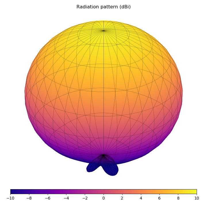
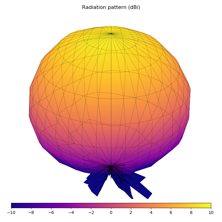
Simulated (HFSS) |
Measured (anechoic chamber, averaged over full bandwidth) |
|
Simulated 3D radiation pattern. |
Measured 3D radiation pattern, by Antenna Test Lab. |
|
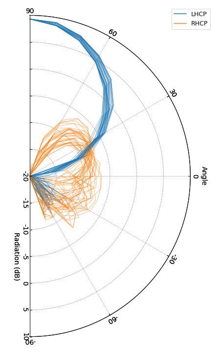
Simulated vertical cross-sections. |
Measured vertical cross-sections, by Antenna Test Lab. |

Note: You are free to use these images for marketing purposes if you are selling Triple Feed Patch antennas as long as you link back to this page. Additionally, if you use the images based on the anechoic chamber measurements from Antenna Test Lab, please link back to antennatestlab.com as well.
Animated 3D radiation pattern, by Antenna Test Lab.
VNA measurements
|
VNA measurements (S-parameters). S11 and S22 indicate the reflected power at port 1 and 2 respectively. S12 and S21 indicate how much power is leaking from one port to the other. |
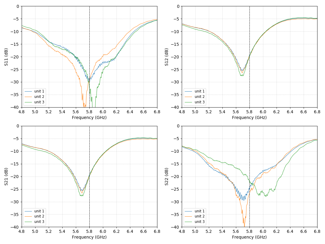
This gives you an idea of the kind of variations you can expect for hand-assembled antennas. I suspect that most of the variation is caused by the surface-mount SMA connectors since those were soldered by hand, and it's difficult to accurately control the amount of solder when you can't even see the center pin. This would explain why there is a lot of variation in S11 and S22, but almost no variation in S12 and S21. Based on S12 and S21 (which should be more reliable), the center frequency appears to be close to 5.7 GHz, which I suspect is a result of inaccurate spacing of the PCBs. The 4 mm spacers which I used to construct these units somehow resulted in a final spacing closer to 4.2 mm in reality.
Where can I buy one?
I have no plans to manufacture these antennas myself, I'm hoping that other antenna builders will pick up this design and start selling it.
The following manufacturers are selling the Triple Feed Patch antenna:
|
Manufacturer |
Price* (USD) |
LHCP |
RHCP |
Hybrid |
SMA male |
SMA female |
RP-SMA male |
RP-SMA female |
Notes |
|
$9.85 |
|
|
|
|
|
|
|
Includes semi-rigid coax (SMA male – SMA male or SMA male – RP-SMA female). | |
|
$21.99 |
|
|
|
|
|
|
|
Includes semi-rigid coax (SMA male – SMA male or SMA male – RP-SMA female). | |
|
$8.78 |
|
|
|
|
|
|
|
Only ships to the Czech Republic and Slovakia. | |
|
$22.5 |
|
|
|
|
|
|
|
Includes semi-rigid coax (SMA male – SMA male). | |
|
$15 |
|
|
|
|
|
|
|
Includes semi-rigid coax. | |
|
$15.29 |
|
|
|
|
|
|
|
Includes semi-rigid coax (SMA male – SMA male). | |
|
$15.28 |
|
|
|
|
|
|
|
Includes semi-rigid coax (SMA male – SMA male). |


* Based on listed price and exchange rate at time of writing. May be outdated. Shipping not included.
If you are a manufacturer who is selling this design, feel free to email me or leave a comment below.
You can also just build them yourself, it's really not that hard. Just download the design files and follow the instructions below.
License

This work is licensed under a Creative Commons Attribution-ShareAlike 4.0 International License.
This means you are free to use this design in any way you like (this includes commercial use) as long as you credit us (Maarten Baert and Robin Theunis). If you choose to modify the design files, you should share the modified design files under the same license.
Design files
Download Triple Feed Patch 1 design files (includes LHCP, RHCP and hybrid variant)
Important: This antenna will only work properly when manufactured and assembled correctly. This is not just a regular circuit board, read the instructions below!
Important: If you use Elecrow to manufacture these PCBs, you should add the following note to your order to let them know that the screw holes must be unplated:
The second PCB (pcb_tfp_1_part2_*.zip) has a separate file for non-plated-through holes (pcb_tfp_1_part2_*-npth.txt).
Parts
If you decide to build this antenna, you will need the following parts:
-
PCBs: Manufacturers will make these for you if you send them the Gerber files which are included in the design files above. I used Elecrow for my prototypes, they will make 10 PCBs for $10. That means you end up paying $2 per antenna (it gets much cheaper if you make them in larger quantities). The PCBs must use 1.0 mm thickness FR4 material, not the regular 1.6 mm thickness. The correct thickness is critical, if you get this wrong the design won't work properly at all! Regarding copper thickness, 35 µm (1 oz) is fine. Thicker copper tracks won't improve the efficiency at RF frequencies due to the skin effect. The design is tuned for standard FR4, but there may be small variations between different FR4 manufacturers which can result in a shift in the center frequency of the antenna. I specifically made sure that the design isn't too sensitive to material variations, so this shouldn't be a huge problem, but you should still avoid manufacturers that use special materials with different dielectric constants than regular FR4.
-
Copper wire: Regular copper wire with a 1.0 mm diameter is used to create the three feed pins. Tin-plated copper or similar is also fine, but don't use iron or steel wire.
-
SMA connector (vertical type): For performance reasons I used surface-mount vertical SMA connectors. I used this for my prototypes. They cost $8 for 10 pieces, so that's $1.6 per antenna. Soldering these requires a hot air rework station or reflow oven, because you can't reach the center pin with a regular soldering iron. I'm planning to make some variants with simpler edge-mount connectors that are easier to solder, but this will result in longer tracks over FR4 which means higher loss.
-
SMA connector (edge mount type): The advantage of the edge mount type is that you don't need a hot air rework station or reflow oven. This type of connector is also somewhat less likely to break. The disadvantage is that you need slightly longer PCB tracks, which results in higher loss. You can buy these connectors from many sources (example), but make sure that you get a type made for 1.0 mm PCBs, not the default 1.6 mm! Typically these connectors will have a pin spacing of 1.1 – 1.2 mm to accommodate small manufacturing variations.
Assembly
The PCBs need to be spaced accurately to get good results. The correct spacing is 4 mm. You can buy metal spacers of this height to make this easier. Ideally you need to get these distances right within a 0.1 mm tolerance.
I will add more detailed instructions when I have more time. If you're wondering how you are supposed to solder the center pin of the SMA connectors, there are two ways: pre-tin both the pad and the pin, or use solder paste (I prefer the first option). Place the connector on top of the PCB, and heat it up with a hot air rework station until they join. Adding flux helps. Use tweezers to align the connector properly if necessary. Finally use a regular soldering iron to solder the large ground pad to the connector.
Assembly jig
David Lewis (FarVew) created a nice laser-cut assembly jig which is especially useful if you want to assemble several of these antennas. It's not strictly required though, you can also assemble the antenna without this, it just takes longer.
|
|
|
|

Download Triple Feed Patch 1 assembly jig design files
Comments
Metrox |
Comment #1: Sun, 30 Jul 2017, 0:22 (GMT+1, DST) Just want to try to make it with my self. I am hobbyist, not a manufacturer. Thank you. |
Rjxhobby |
Comment #2: Sun, 30 Jul 2017, 3:24 (GMT+1, DST) it is michael from RJXHOBBY, we are manufacture, we would like to pick up this design, just to confirm, need we get authorization from you to design and sell this, thanks, your quick reply will be highly appreciated. Best Regards, RJX HOBBY CO., LTD |
Maarten BaertAdministrator |
Comment #3: Sun, 30 Jul 2017, 17:13 (GMT+1, DST) Quote: Metrox
Just want to try to make it with my self. I am hobbyist, not a manufacturer. Thank you. The correct settings are: Quote: Rjxhobby
it is michael from RJXHOBBY, we are manufacture, we would like to pick up this design, just to confirm, need we get authorization from you to design and sell this, thanks, your quick reply will be highly appreciated. No authorization is required, you are free to manufacture these as long as you do what the license requires: Quote
This work is licensed under a Creative Commons Attribution-ShareAlike 4.0 International License. This means you are free to use this design in any way you like (this includes commercial use) as long as you credit us (Maarten Baert and Robin Theunis). If you choose to modify the design files, you should share the modified design files under the same license. |
Metrox |
Comment #4: Mon, 31 Jul 2017, 9:37 (GMT+1, DST) Thank you for answer, Can you tell what better wire to get (to connect Patch with goggles). Or you made it by yourself as well ? |
Rjxhobby |
Comment #5: Tue, 1 Aug 2017, 11:27 (GMT+1, DST) Quote: Maarten Baert
No authorization is required, you are free to manufacture these as long as you do what the license requires: Quote
This work is licensed under a Creative Commons Attribution-ShareAlike 4.0 International License. This means you are free to use this design in any way you like (this includes commercial use) as long as you credit us (Maarten Baert and Robin Theunis). If you choose to modify the design files, you should share the modified design files under the same license. thanks for your answer, i really appreciate it. Best Regards, RJX HOBBY CO., LTD Last modified: Tue, 1 Aug 2017, 23:06 (GMT+1, DST) |
Maarten BaertAdministrator |
Comment #6: Tue, 1 Aug 2017, 23:05 (GMT+1, DST) Quote: Metrox
Thank you for answer, Can you tell what better wire to get (to connect Patch with goggles). Or you made it by yourself as well ? I used the same coax as what I used for the Pagoda antenna and attached the connectors myself. It's RG402 and corresponding soldered SMA connectors. Ebay links here and here. |
Race412 |
Comment #7: Fri, 4 Aug 2017, 0:38 (GMT+1, DST) I'm not sure if you have a section yet for a list of retailers, or plan too. If so, I was wondering if my store could be added? We have a preorder and expect stock to be received with a week-ish. Thank you https://squareup.com/store/room-412/ |
Fpvbrain |
Comment #8: Fri, 4 Aug 2017, 12:00 (GMT+1, DST) Hey Maarten |
Fpvbrain |
Comment #9: Sat, 5 Aug 2017, 15:27 (GMT+1, DST) Triple Feed Patch antenna Spacer ShareAlike https://www.thingiverse.com/thing:2468349 |
Tomkanovik |
Comment #10: Mon, 7 Aug 2017, 20:04 (GMT+1, DST) Quote: Fpvbrain
Triple Feed Patch antenna Spacer ShareAlike https://www.thingiverse.com/thing:2468349 Maarten? Will it not affect the functionality of the antenna? |
Metrox |
Comment #11: Thu, 10 Aug 2017, 9:00 (GMT+1, DST) Tomkanovik, Use it as spacer wile weld. |
Zingaros |
Comment #12: Thu, 10 Aug 2017, 11:07 (GMT+1, DST) Hello Maarten, all, Thanks again to release wonderful new gadget to the community! Anyone interested to sell the raw PCBs by units for Europe: I m not really up for 10 pieces. Thanks |
Rjxhobby |
Comment #13: Thu, 10 Aug 2017, 11:08 (GMT+1, DST) Hi, we have made this triple feed patch antenna already. michael@rxjhobby.com |
Zoorgaz |
Comment #14: Fri, 11 Aug 2017, 13:13 (GMT+1, DST) Hello. Awesome antenna! Do i assume correctly due to the name, I can actually use this antenna as LHCP and RHCP in 2xMiMO? |
Tomkanovik |
Comment #15: Fri, 11 Aug 2017, 14:02 (GMT+1, DST) Quote: Zingaros
Hello Maarten, all, Thanks again to release wonderful new gadget to the community! Anyone interested to sell the raw PCBs by units for Europe: I m not really up for 10 pieces. Thanks A few of them i have in transit, and i am from czech republic :) |
Zingaros |
Comment #16: Fri, 11 Aug 2017, 15:41 (GMT+1, DST) Quote: Rjxhobby
Hi, we have made this triple feed patch antenna already. michael@rxjhobby.com Thanks Michael: I just ordered one of them. Eager to test them. I will post a short review once tested. |
Maarten BaertAdministrator |
Comment #17: Tue, 15 Aug 2017, 1:58 (GMT+1, DST) Quote: Tomkanovik
Maarten? Will it not affect the functionality of the antenna? It will definitely shift the center frequency. I don't recommend using any spacer, it's really not necessary in my experience. If you really want a spacer, use something with a very low dielectric constant and very low loss, like Styrofoam. Quote: Zoorgaz
Hello. Awesome antenna! Do i assume correctly due to the name, I can actually use this antenna as LHCP and RHCP in 2xMiMO? Yes, if you have a receiver with MIMO support. |
Swiftflying |
Comment #18: Thu, 17 Aug 2017, 5:19 (GMT+1, DST) Dear sir Sorry for bothering you, I just read your the article again , It would be great if you can support us. Hope we can make more cooperation in the future. looking forward to your reply! E-mail: swiftflying@163.com |
Rodyparker |
Comment #19: Wed, 23 Aug 2017, 3:12 (GMT+1, DST) Hello Maarten, do you think a PCB with 0.8mm with 0.5 oz of cooper will be a problem? |
Rjxhobby |
Comment #20: Wed, 23 Aug 2017, 3:47 (GMT+1, DST) Hello Maarten, all, Thanks again to release wonderful new gadget to the community! http://www.rjxhobby.com/rjx-rjx1647 contact michael for dealers price. michael@rjxhobby.com or michael@rjxdrone.com thanks again for wonderful design. Last modified: Mon, 28 Aug 2017, 23:17 (GMT+1, DST) |
Rodyparker |
Comment #21: Thu, 24 Aug 2017, 0:18 (GMT+1, DST) other question, the top pcb has to be 2 layers also? |
Tomkanovik |
Comment #22: Fri, 25 Aug 2017, 10:52 (GMT+1, DST) Hello i add this antenna to my store. here is link http://flytime.cz/product/TRIPLEFEEDPATCH. And i add LHCP pagoda to my Flytime store. :) |
Maarten BaertAdministrator |
Comment #23: Mon, 28 Aug 2017, 23:18 (GMT+1, DST) Quote: Rodyparker
Hello Maarten, do you think a PCB with 0.8mm with 0.5 oz of cooper will be a problem? Yes. This design is made for 1mm FR4 and will not work properly with anything else. Quote: Rodyparker
other question, the top pcb has to be 2 layers also? Not strictly required, but for physical strength it helps a lot to have solder pads on both sides. |
Rjxhobby |
Comment #24: Tue, 29 Aug 2017, 4:24 (GMT+1, DST) we have designed these antenna, you can see my facebook: https://www.facebook.com/rjxhobbyedna or contact my email for special price: edna@rjxdrone.com |
Dave855 |
Comment #25: Tue, 29 Aug 2017, 8:33 (GMT+1, DST) Thanks again Maarten! Far Vew finally got their version up and on! https://farvew.com/home/69-triple-feed-patch-lhcp-and-rhcp.html Thanks Maarten you and Robin have reshaped FPV again! |
Rodyparker |
Comment #26: Sat, 2 Sep 2017, 18:28 (GMT+1, DST) Quote: Maarten Baert
Quote: Rodyparker
Hello Maarten, do you think a PCB with 0.8mm with 0.5 oz of cooper will be a problem? Yes. This design is made for 1mm FR4 and will not work properly with anything else. Quote: Rodyparker
other question, the top pcb has to be 2 layers also? Not strictly required, but for physical strength it helps a lot to have solder pads on both sides. Thank you very musch for the answer, I'm doing a prototype in home with the right board and I also ask to elecrow some pieces. |
Erwin024 |
Comment #27: Sat, 9 Sep 2017, 6:17 (GMT+1, DST) Hi, when using triple feed patch antenna, do I still have to use diversity module? |
Rjxhobby |
Comment #28: Sat, 9 Sep 2017, 7:30 (GMT+1, DST) we have this Triple Feed Patch antenna https://www.facebook.com/rjxhobby michael@rjxhobby.com |
Feket663 |
Comment #29: Sat, 16 Sep 2017, 19:58 (GMT+1, DST) Hi! I'd like buy this great designed antenna. But have a question: can I use a cheap 50 ohm SMA dummy load from ebay or aliexpress. My biggest problem is this dummy loads specified only 3 GHz. For example: link Can I use it? Last modified: Mon, 23 Oct 2017, 1:17 (GMT+1, DST) |
Flick1 |
Comment #30: Wed, 20 Sep 2017, 9:24 (GMT+1, DST) Hi Maarten, |
Gs550t1981 |
Comment #31: Tue, 3 Oct 2017, 4:52 (GMT+1, DST) I'm not to good at understanding the graphs. What is the radiation pattern? When pointing the antenna straight ahead is it basically 55° verticle and horizontal? What makes them better than say a crosshair? I am asking not to bust your chops. I love the Pagodas and are the only antenna I use. I picked this up and want to know what it would be ideal to use for... Thanks |
Fpvbrain |
Comment #32: Sun, 15 Oct 2017, 3:08 (GMT+1, DST) It will definitely shift the center frequency LOL since when determined PLA or ABS the center frequency Maarten Baert I would like gladly times a field strength test of ABS or PLA from you see which you can send me gladly to info@FPV-BRAIN.net then you may not synonymous PCB More paint. :-) |
Fpvbrain |
Comment #33: Sun, 15 Oct 2017, 3:21 (GMT+1, DST) Conductivity of insulators κ in S / cm rubber10-16 polystyrene 10-18 porcelain 10-15 |
Akinys |
Comment #34: Sat, 21 Oct 2017, 20:19 (GMT+1, DST) If to use only RHCP, what option will be best: |
Maarten BaertAdministrator |
Comment #35: Sun, 29 Oct 2017, 2:05 (GMT+1, DST) Quote: Erwin024
Hi, when using triple feed patch antenna, do I still have to use diversity module? Typically directional antennas like these are combined with an omnidirectional antenna (like the Pagoda) in a diversity setup. You can use them without diversity if you want, but then you need to make sure that you are always pointing the antenna in the right direction. Any diversity module should work with any antenna, as long as the connectors are compatible. Quote: Feket663
Hi! I'd like buy this great designed antenna. But have a question: can I use a cheap 50 ohm SMA dummy load from ebay or aliexpress. My biggest problem is this dummy loads specified only 3 GHz. For example: link Can I use it? Any 50 ohm terminator should work, it's not critical. You can even use the antenna without a terminator, it will still work fine, the axial ratio will just be slightly worse because the opposite polarization will be reflected instead of absorbed. Quote: Flick1
Hi Maarten, The problem is that the through-hole connectors would need a hole in the ground plane, which interferes with the patch antenna on the other side. It's also really difficult to get a good 50 ohm match with those connectors at high frequencies. Quote: Gs550t1981
I'm not to good at understanding the graphs. What is the radiation pattern? When pointing the antenna straight ahead is it basically 55° verticle and horizontal? What makes them better than say a crosshair? I am asking not to bust your chops. I love the Pagodas and are the only antenna I use. I picked this up and want to know what it would be ideal to use for... Thanks If you point the patch straight at the other antenna, that's considered 0 degrees (the top of the radiation pattern graph). These aren't necessarily better than crosshairs, but they are easier to manufacture because they aren't as sensitive to deviations in length of the radiating elements. Also, this antenna achieves a good axial ratio across the entire bandwidth, whereas crosshairs typically only get a good axial ratio close to their center frequency. Finally, this antenna has a good axial ratio in all directions, not just when it is pointed straight at the other antenna but also at an angle. This is rarely the case for rectangular patches or crosshair antennas. Quote: Fpvbrain
It will definitely shift the center frequency LOL since when determined PLA or ABS the center frequency Maarten Baert I would like gladly times a field strength test of ABS or PLA from you see which you can send me gladly to info@FPV-BRAIN.net then you may not synonymous PCB More paint. :-) Quote: Fpvbrain
Conductivity of insulators κ in S / cm rubber10-16 polystyrene 10-18 porcelain 10-15 ... what? Conductivity is irrelevant in this context, what matters is dielectric constant and loss tangent. The dielectric constant of air is 1.0, for plastic it is usually somewhere between 2.0 and 3.0 depending on the type and density. The resonance frequency of a patch is inversely proportional to the square root of the dielectric constant. This is basic antenna theory which you can find in any book that discusses patch antennas. For example, if you used a polyethylene spacer (dielectric constant 2.26), you will shift the resonant frequency from 5.8 GHz down to 3.86 GHz. Of course the feed network isn't affected by this since it is on the other side of the PCB. So you now have an antenna with a 5.8 GHz feed network and a 3.86 GHz patch, so your antenna will be pretty much useless. The Pagoda was less susceptible to this because the space between the plates contains only a small part of the electromagnetic fields. As a result you could put a spacer between the two and still get an antenna that was usable. This is not the case for patch antennas, where 99% of the electromagnetic field is concentrated between the two plates. Quote: Akinys
If to use only RHCP, what option will be best: Option 3, but if you don't want to add the SMA connector, you could also solder a 50 ohm SMD resistor directly to the PCB. Removing the connector is also possible, but don't remove the feed line. The feed network in the center has been designed with the feed line taken into account, removing it will affect the performance. An even better option is to use an alternative feeding network that is LHCP or RHCP only, but I haven't made that one public yet because I didn't have time. |
Ryan |
Comment #36: Tue, 31 Oct 2017, 14:29 (GMT+1, DST) What is center frequency? I run my vtx on channel 5658. Am I off center? Is center as close to 5800 as possible? Does it matter how the patch sits on the goggles ? Is there a up or down/top or bottom of the patch? Last modified: Wed, 1 Nov 2017, 23:12 (GMT+1, DST) |
Vlado |
Comment #37: Thu, 2 Nov 2017, 20:25 (GMT+1, DST) Would it work well if I solder RG402 cable directly to the PCB? How about soldering rx5808 video rx module on the antenna? :D |
Maarten BaertAdministrator |
Comment #38: Sat, 4 Nov 2017, 3:43 (GMT+1, DST) Quote: Ryan
What is center frequency? I run my vtx on channel 5658. Am I off center? Is center as close to 5800 as possible? Does it matter how the patch sits on the goggles ? Is there a up or down/top or bottom of the patch? The center frequency is 5.8 GHz. As you can see in the specs, the bandwidth is 660 MHz (5.47 – 6.13 GHz), so 5.658 GHz will work fine. There is no top/bottom, just point the patch in the direction of the transmitter and you are fine. Quote: Vlado
Would it work well if I solder RG402 cable directly to the PCB? How about soldering rx5808 video rx module on the antenna? :D That won't work well with the current PCB layout. The matching will be bad. The layout you see now is specifically tuned to match well to those vertical SMA connectors. |
Andymidtf |
Comment #39: Thu, 16 Nov 2017, 20:41 (GMT+1, DST) Quote: Maarten Baert
The correct settings are: - PCB Size: "5cm Max * 5cm Max" (part1) / "10cm Max * 10cm Max" (part2) Hi Maarten, I am ordering from Seeed, there the PCB size can be much smaller - from the .dxf files I see part one is 24.9mm wide, and part 2 is 60.0mm wide - any reason not to use these sizes in the order page? Thanks very much! Andy PD do you have a paypal or accept bitcoin (better some other vcoin with todays tx rates!), even thou you offer these open source, I really think you deserve some renumeration for your excellent work! |
Actuna |
Comment #40: Sun, 26 Nov 2017, 22:03 (GMT+1, DST) Hello ... I would like to inform you about the production and sale of the Triple Feed Patch (hybrid): Manufacturer: ACTUNA URL: https://actuna.com/Antenna-Triple-Feed-Patch-1-5-8GHz-RHCP-LHCP-p13210 Price: 9,85 $ - hybrid Notes: Each antenna is measured individually and gets its own parameters tab. SMA and RP-SMA - Includes semi-rigid coax (SMA male – SMA male or SMA male - RP-SMA female). Fast delivery in the EU (3-10 days). Contacts: actuna@actuna.pl PS: We produced a modified version of the Triple Feed Patch (hybrid) antenna - a diameter of 45mm. We are now finishing the tests of this antenna, the results are positive. Last modified: Sun, 26 Nov 2017, 22:05 (GMT+1, DST) |
Prxbl |
Comment #41: Mon, 27 Nov 2017, 13:06 (GMT+1, DST) Since male SMA terminators are hard to find can I use a 49.9ohm resistor to terminate one of the sides permanently? I plan to remove the SMA connector and just solder an SMD resistor between signal and ground in the place of the old connector. |
Maarten BaertAdministrator |
Comment #42: Wed, 29 Nov 2017, 3:34 (GMT+1, DST) Quote: Andymidtf
Hi Maarten, I am ordering from Seeed, there the PCB size can be much smaller - from the .dxf files I see part one is 24.9mm wide, and part 2 is 60.0mm wide - any reason not to use these sizes in the order page? Thanks very much! Andy PD do you have a paypal or accept bitcoin (better some other vcoin with todays tx rates!), even thou you offer these open source, I really think you deserve some renumeration for your excellent work! If the manufacturer asks for the exact size, then you should do that. Elecrow doesn't do this though. If they don't offer panelization, then don't worry about it. Also, I don't accept donations, but thanks anyway :). Quote: Prxbl
Since male SMA terminators are hard to find can I use a 49.9ohm resistor to terminate one of the sides permanently? I plan to remove the SMA connector and just solder an SMD resistor between signal and ground in the place of the old connector. You should just get the LHCP or RHCP variant instead of the hybrid if that is what you want. But yes, you can do this. It won't be perfect because the footprint is designed to cancel out some of the mismatch of the connector, but it will be pretty close. Last modified: Wed, 29 Nov 2017, 3:37 (GMT+1, DST) |
Actuna |
Comment #43: Fri, 1 Dec 2017, 15:12 (GMT+1, DST) Quote: Actuna
We produced a modified version of the Triple Feed Patch (hybrid) antenna - a diameter of 45mm. We are now finishing the tests of this antenna, the results are positive. |
Race412 |
Comment #44: Tue, 5 Dec 2017, 19:26 (GMT+1, DST) Hello Maarten, https://race412.com/product/triple-feed-patch/ Thank You |
Maarten BaertAdministrator |
Comment #45: Wed, 6 Dec 2017, 1:10 (GMT+1, DST) Quote: Race412
Hello Maarten, https://race412.com/product/triple-feed-patch/ Thank You Can you specify which connectors you are using on the PCB as well as the coax? Is the PCB connector also RP-SMA or just one of the connectors on the coax? |
Race412 |
Comment #46: Sat, 6 Jan 2018, 1:50 (GMT+1, DST) Quote: Maarten Baert
Quote: Race412
Hello Maarten, https://race412.com/product/triple-feed-patch/ Thank You Can you specify which connectors you are using on the PCB as well as the coax? Is the PCB connector also RP-SMA or just one of the connectors on the coax? Yes, sorry for the long response time, we make the plate exactly the way you do for the connectors, but the coax can be made for either an SMA or RPSMA receiver. Edit: typo Last modified: Sat, 6 Jan 2018, 1:51 (GMT+1, DST) |
Timkostka |
Comment #47: Sun, 4 Feb 2018, 18:33 (GMT+1, DST) Can I remove the 4 holes on this without affecting the performance? Any guesses on how the performance would change if I made the bottom PCB 57.5mm in diameter instead of 60mm? (to fit 2 into a 10x10cm panel) Last modified: Sun, 4 Feb 2018, 22:15 (GMT+1, DST) |
Maarten BaertAdministrator |
Comment #48: Tue, 13 Feb 2018, 1:29 (GMT+1, DST) Quote: Timkostka
Can I remove the 4 holes on this without affecting the performance? Any guesses on how the performance would change if I made the bottom PCB 57.5mm in diameter instead of 60mm? (to fit 2 into a 10x10cm panel) The mounting holes have no impact on performance. Changing the diameter has a small effect on the directivity, but 2.5mm won't make a significant difference. |
Goatzilla |
Comment #49: Thu, 15 Mar 2018, 4:30 (GMT+1, DST) On the antenna it says, "Keep this area clear". What exactly does that mean? For my setup it's easiest if I use a right angle adapter and send the cable out the side. Is that going to cause problems? |
Maarten BaertAdministrator |
Comment #50: Sun, 25 Mar 2018, 1:21 (GMT+1, DST) Quote: Goatzilla
On the antenna it says, "Keep this area clear". What exactly does that mean? For my setup it's easiest if I use a right angle adapter and send the cable out the side. Is that going to cause problems? No, as long as you keep the cable and connector at least 1 cm away from the tracks it's not going to have an impact. |
Xaled |
Comment #51: Sun, 1 Apr 2018, 20:56 (GMT+1, DST) Hi Maarten, |
Maarten BaertAdministrator |
Comment #52: Sun, 15 Apr 2018, 14:26 (GMT+1, DST) Quote: Xaled
Hi Maarten, I don't have enough time to redesign this antenna for all possible frequencies. But it shouldn't be too hard to do this yourself, especially if you use the simpler one-port feed network instead of the hybrid LHCP/RHCP version. |
Prouser27 |
Comment #53: Wed, 30 May 2018, 14:48 (GMT+1, DST) Hello Maarten! On the vertical cross-section image it looks like as the LHCP is more "stronger" as the RHCP polarization? The LHCP polarization looks like an big signal bubble in on direction and the RHCP much smaller. Or are the two polarizations equally strong? Last modified: Wed, 30 May 2018, 14:50 (GMT+1, DST) |
Maarten BaertAdministrator |
Comment #54: Fri, 1 Jun 2018, 1:43 (GMT+1, DST) Quote: Prouser27
Hello Maarten! On the vertical cross-section image it looks like as the LHCP is more "stronger" as the RHCP polarization? The LHCP polarization looks like an big signal bubble in on direction and the RHCP much smaller. Or are the two polarizations equally strong? The images show the radiation pattern when a signal is applied to the LHCP port and the RHCP port has only a 50 ohm terminator connected to it. It's not supposed to transmit any RHCP radiation. If you swap the signal to the other port, LHCP and RHCP will be swapped as well. So LHCP and RHCP are equally strong, at least when using the right port. |
Sebbaling |
Comment #55: Mon, 29 Oct 2018, 15:51 (GMT+1, DST) First of all, thank you for your great work Maarten! I have two questions: 1) would it be problematic if i connect the antenna directly to a 45° angle adapter on my receiver without the coax cable? 2) is the antenna supposed to be oriented in a specific manner (like one site has to be towards the sky and the other to the ground) or does it only has to be pointed toward the transmitting antenna no matter the rest of the orientation? regards |
Maarten BaertAdministrator |
Comment #56: Tue, 30 Oct 2018, 1:28 (GMT+1, DST) Quote: Sebbaling
First of all, thank you for your great work Maarten! I have two questions: 1) would it be problematic if i connect the antenna directly to a 45° angle adapter on my receiver without the coax cable? 2) is the antenna supposed to be oriented in a specific manner (like one site has to be towards the sky and the other to the ground) or does it only has to be pointed toward the transmitting antenna no matter the rest of the orientation? regards 1) This is fine. Just keep enough distance between the receiver and the tracks on the PCB. Ideally 1cm or more. 2) It doesn't matter as long as you point it at the transmitter. Last modified: Tue, 30 Oct 2018, 1:29 (GMT+1, DST) |
Dave |
Comment #57: Sun, 25 Nov 2018, 3:07 (GMT+1, DST) Interesting and quite simple design! Last modified: Mon, 26 Nov 2018, 21:30 (GMT+1, DST) |
Esfateev |
Comment #58: Tue, 25 Dec 2018, 13:01 (GMT+1, DST) Hi! Thank you for your hard work! You've made awesome antennas! |
Yoppy |
Comment #59: Fri, 4 Jan 2019, 0:58 (GMT+1, DST) Hi Maarten, I have made several pieces of RHCP version of triple feed patch antenna. However, all of the antenna I make, center frequency is consistently at around 5.2-5.3 GHz. At 5.8 GHz, the S11 is around 19-14 dB. What would you suggest? Decrease the patch spacing? |
Maarten BaertAdministrator |
Comment #60: Thu, 10 Jan 2019, 22:33 (GMT+1, DST) Quote: Esfateev
Hi! Thank you for your hard work! You've made awesome antennas! Yes, this is possible, but you will have to re-simulate the feed network, which is quite tricky. Just scaling it by a fixed factor won't be very accurate, especially for the hybrid variant. Quote: Yoppy
Hi Maarten, I have made several pieces of RHCP version of triple feed patch antenna. However, all of the antenna I make, center frequency is consistently at around 5.2-5.3 GHz. At 5.8 GHz, the S11 is around 19-14 dB. What would you suggest? Decrease the patch spacing? Yes, decreasing the space between the PCBs will increase the center frequency. Your jig may be inaccurate, maybe the spacing is already too high. Try measuring it with calipers. If that doesn't explain it, perhaps the manufacturer has switched to a different brand of FR4. Last modified: Thu, 10 Jan 2019, 22:36 (GMT+1, DST) |
Yoppy |
Comment #61: Sun, 13 Jan 2019, 17:02 (GMT+1, DST) Thank you Maarten for your reply. Another related question, if I decrease the patch spacing in order to get higher center frequency, but how does it affect other performance parameters, such as axial ratio, radiation pattern, etc? Will they be compromized? |
Maarten BaertAdministrator |
Comment #62: Sat, 19 Jan 2019, 4:18 (GMT+1, DST) Quote: Yoppy
Thank you Maarten for your reply. Another related question, if I decrease the patch spacing in order to get higher center frequency, but how does it affect other performance parameters, such as axial ratio, radiation pattern, etc? Will they be compromized? I don't think they will change significantly. The axial ratio is determined mostly by the feed network. Of course if you try to use the feed network at a frequency significantly different from what it was designed for, then it may not work as well. Last modified: Sat, 19 Jan 2019, 4:19 (GMT+1, DST) |
Guitartoys |
Comment #63: Sat, 11 Jul 2020, 0:07 (GMT+1, DST) Hi, I've got an interesting application here. My son is a Precision Rifle Shooting competitor. So he needs to practice out to like 600 yards. What I've done is CAD'd up a case for an FPV camera and a 2W transmitter along with an FPV receiver/monitor. The camera will be down by the target and the receiver/monitor next to him. I picked up a pair of these patch antennas, and have one installed on the receiver and it works great. I just wanted to ask if it is safe to use the patch antenna on the transmitter as well. As the camera is static on a tripod, and can be aimed pretty decently towards the receiver as it is line of sight. So the question is, is it OK to use this antenna on a transmitter. Thanks. |
Maarten BaertAdministrator |
Comment #64: Sat, 11 Jul 2020, 23:05 (GMT+1, DST) Quote: Guitartoys
Hi, I've got an interesting application here. My son is a Precision Rifle Shooting competitor. So he needs to practice out to like 600 yards. What I've done is CAD'd up a case for an FPV camera and a 2W transmitter along with an FPV receiver/monitor. The camera will be down by the target and the receiver/monitor next to him. I picked up a pair of these patch antennas, and have one installed on the receiver and it works great. I just wanted to ask if it is safe to use the patch antenna on the transmitter as well. As the camera is static on a tripod, and can be aimed pretty decently towards the receiver as it is line of sight. So the question is, is it OK to use this antenna on a transmitter. Thanks. 'Safe' is a relative thing - it will not damage the transmitter, however because of the ~10dB antenna gain, it will result in the equivalent of a 17W transmitter. This is a lot higher than the legal limit in most places (unless you have an amateur radio license, then different rules apply). Depending on the chosen frequency, your signal may cause interference with weather radar. This is less likely to be a problem if you stay within the ISM band though (5.725 – 5.875 GHz). In any case I would suggest not standing directly in front of the antenna at close range if you do this. But power drops with the square of the distance, so simply moving 3x further away from it will reduce the power by 9x which is about the same as what you would have had with an omnidirectional antenna. Last modified: Sat, 11 Jul 2020, 23:23 (GMT+1, DST) |
Flo |
Comment #65: Fri, 7 Aug 2020, 18:11 (GMT+1, DST) Hi Maarten, that’s a pretty cool design, specially the power divider. I would like to built one of this kind for a different antenna (in 900MHz ISM range). Best regards |
Maarten BaertAdministrator |
Comment #66: Fri, 7 Aug 2020, 23:55 (GMT+1, DST) Quote: Flo
Hi Maarten, that’s a pretty cool design, specially the power divider. I would like to built one of this kind for a different antenna (in 900MHz ISM range). Best regards You can find them here. But I don't think the design will be very useful at 900 MHz, it would be very large which makes the PCBs rather expensive. Last modified: Fri, 7 Aug 2020, 23:55 (GMT+1, DST) |
Flo |
Comment #67: Sat, 8 Aug 2020, 9:01 (GMT+1, DST) Hi Maarten, thanks for the fast reply - but the file you attached was from the pagoda antenna, what I would like to try is the triple feed patch antenna. Could you send me the hfss file for tripple feed patch ant (or one with the feed network)? I'm triying to figure out the spliiter function, is it some kind of combined simplified ratrace or how would you describe it? By the way - I took a look at the Pagoda Design - I've seen that you used a length based refinement for the copper structures. Have you tried a surface approximation for the curved elements (I've made good results for curved geometries with a Surf approximation (normal deviation around 5deg) => select part, RMB, Surface Approximation, Manual Settings, Normal Deviation) Best Regards |
Maarten BaertAdministrator |
Comment #68: Sat, 8 Aug 2020, 15:58 (GMT+1, DST) Quote: Flo
Hi Maarten, thanks for the fast reply - but the file you attached was from the pagoda antenna, what I would like to try is the triple feed patch antenna. Sorry, wrong file - the correct one is here. Because of the complexity of the model, it is split over multiple files:
Quote: Flo
Could you send me the hfss file for tripple feed patch ant (or one with the feed network)? I'm triying to figure out the spliiter function, is it some kind of combined simplified ratrace or how would you describe it? It's a custom design, developed primarily by numerical optimization. I looked for existing hybrid designs but couldn't find anything that did what I needed. I started off with a 3-section branch-line coupler with an extra output, which gave me something that looked a bit like what I needed, and then just optimized the lengths and impedances hoping that it would converge to a reasonable result - and somehow that worked perfectly from the very first attempt. I started with ideal transmission lines in ADS to find the correct lengths and impedances that would give me the S-parameters I wanted, then converted that to a curved version in HFSS that matches the physical position of the feed pins, and re-optimized that one to compensate for the parasitic coupling that's created by placing all the tracks so close together. Quote: Flo
By the way - I took a look at the Pagoda Design - I've seen that you used a length based refinement for the copper structures. Have you tried a surface approximation for the curved elements (I've made good results for curved geometries with a Surf approximation (normal deviation around 5deg) => select part, RMB, Surface Approximation, Manual Settings, Normal Deviation) Best Regards I added the manual refinement steps mainly to improve the convergence speed by adding smaller elements near the copper edges (where the electrical fields are stronger), not because of the curvature. Without manual refinement HFSS needs a lot of automatic refinement steps before it stabilizes, and I noticed that the results weren't always equally accurate. This is a big problem when doing numerical optimization, it's actually preferable to have a large, consistent error than a small error that varies significantly between simulations, because if the error is consistent, it doesn't really affect the optimization process. Manual refinement seems to help a lot here, there's far less random 'meshing noise' in the simulation output because the meshing is more deterministic. |
Bseishen |
Comment #69: Thu, 17 Sep 2020, 21:34 (GMT+1, DST) You see any issues with making a single pcb with 2x8 array of these? This would be for a 8ch diversity |
Maarten BaertAdministrator |
Comment #70: Fri, 18 Sep 2020, 22:36 (GMT+1, DST) Quote: Bseishen
You see any issues with making a single pcb with 2x8 array of these? This would be for a 8ch diversity 8-channel diversity doesn't make much sense, why would you expect one of those eight antennas to provide a substantially better signal than the others when they are all pointed in the same direction? Or did you mean 8-channel beam steering or MIMO? That would make more sense and should work at least in theory. Just follow the usual rules with regard to patch spacing. If you just want a more directional version then I recommend the triple feed patch array instead, the hexagonal arrangement produces much better results than a regular grid and it only needs one input feed. |
Kaanfelan |
Comment #71: Tue, 3 Nov 2020, 7:27 (GMT+1, DST) Hello there |
Maarten BaertAdministrator |
Comment #72: Tue, 3 Nov 2020, 23:39 (GMT+1, DST) Quote: Kaanfelan
Hello there As long as you don't reduce the size of the copper ground plane, it won't make a significant difference. |
Anand_kachale |
Comment #73: Thu, 14 Jan 2021, 8:17 (GMT+1, DST) Hi I am a hobbyist and I wanted to try the antenna. I m modifying the design just a little (maybe that isn't even called modification) by panelizing one patch and multiple pagoda on a single board to reduce cost per unit. Hope there isn't any conflict doing so. Please let me know if there is any I will surely change the design. I was hoping to sell the extra antennas that will be made in my local community. Thanks in advance for your quick reply. |
Maarten BaertAdministrator |
Comment #74: Wed, 3 Feb 2021, 12:49 (GMT+1, DST) Quote: Anand_kachale
Hi I am a hobbyist and I wanted to try the antenna. I m modifying the design just a little (maybe that isn't even called modification) by panelizing one patch and multiple pagoda on a single board to reduce cost per unit. Hope there isn't any conflict doing so. Please let me know if there is any I will surely change the design. I was hoping to sell the extra antennas that will be made in my local community. Thanks in advance for your quick reply. That's fine :). |
Afaf_prince |
Comment #75: Thu, 16 Feb 2023, 23:31 (GMT+1, DST) Hi, there is a website called kembros.github which generates patch antenna. It has a calculator that helps to set the di-electric value that is the thickness of the pcb used. So my local designer has least 1.2mm thick board. And I have generated the design for 1.2mm board. Would this called any problem for the antenna? And since I'm using 1.2mm board, should the distance between top plate and bottom plate be still 3mm or 2.8mm? Please reply. |
Maarten BaertAdministrator |
Comment #76: Sat, 15 Apr 2023, 22:11 (GMT+1, DST) Quote: Afaf_prince
Hi, there is a website called kembros.github which generates patch antenna. It has a calculator that helps to set the di-electric value that is the thickness of the pcb used. So my local designer has least 1.2mm thick board. And I have generated the design for 1.2mm board. Would this called any problem for the antenna? And since I'm using 1.2mm board, should the distance between top plate and bottom plate be still 3mm or 2.8mm? Please reply. I don't know what website you are referring to, but I can say that the Triple Feed Patch will not work properly with different PCB thicknesses. Not because of the patch itself (it isn't very sensitive to PCB thickness) but because of the feed network on the back side, which depends on the precise PCB thickness to create transmission lines with various impedances. |
Roman20 |
Comment #77: Fri, 24 Nov 2023, 2:57 (GMT+1, DST) I just made four of the edge design. Thank you for sharing the design! |
Hfan |
Comment #78: Sat, 2 Dec 2023, 4:24 (GMT+1, DST) Hi Maarten, First of all, thanks for the design! I'm trying to DIY the antenna, and might have a naive question, if I directly solder RG178 or other type of coaxial cable onto the place where the SMA connector is supposed to be, would that be OK? Also it is fine if I order the hybrid design from the PCB manufacturer, but only solder (either the SMA connector or coaxial cable) onto 1 of the feed locations? Also, are you aware of the Actuna Triple Feed Patch Mini: https://www.thingiverse.com/thing:2682348. I'm curious if it is in any way associated with your original design, or if you have comments on it, like if there is any performance tradeoff for the smaller size. Again, thanks for open sourcing the design! Gabriel Last modified: Sat, 2 Dec 2023, 4:37 (GMT+1, DST) |
Pcb_peter 126 Com |
Comment #79: Mon, 27 May 2024, 3:19 (GMT+1, DST) Quote: Hfan
Hi Maarten, First of all, thanks for the design! I'm trying to DIY the antenna, and might have a naive question, if I directly solder RG178 or other type of coaxial cable onto the place where the SMA connector is supposed to be, would that be OK? Also it is fine if I order the hybrid design from the PCB manufacturer, but only solder (either the SMA connector or coaxial cable) onto 1 of the feed locations? Also, are you aware of the Actuna Triple Feed Patch Mini: https://www.thingiverse.com/thing:2682348. I'm curious if it is in any way associated with your original design, or if you have comments on it, like if there is any performance tradeoff for the smaller size. Again, thanks for open sourcing the design! Gabriel |
Pcb_peter 126 Com |
Comment #80: Mon, 27 May 2024, 3:19 (GMT+1, DST) Quote: Hfan
Hi Maarten, First of all, thanks for the design! I'm trying to DIY the antenna, and might have a naive question, if I directly solder RG178 or other type of coaxial cable onto the place where the SMA connector is supposed to be, would that be OK? Also it is fine if I order the hybrid design from the PCB manufacturer, but only solder (either the SMA connector or coaxial cable) onto 1 of the feed locations? Also, are you aware of the Actuna Triple Feed Patch Mini: https://www.thingiverse.com/thing:2682348. I'm curious if it is in any way associated with your original design, or if you have comments on it, like if there is any performance tradeoff for the smaller size. Again, thanks for open sourcing the design! Gabriel |
Pcb_peter 126 Com |
Comment #81: Mon, 27 May 2024, 3:21 (GMT+1, DST) Quote: Hfan
Hi Maarten, First of all, thanks for the design! I'm trying to DIY the antenna, and might have a naive question, if I directly solder RG178 or other type of coaxial cable onto the place where the SMA connector is supposed to be, would that be OK? Also it is fine if I order the hybrid design from the PCB manufacturer, but only solder (either the SMA connector or coaxial cable) onto 1 of the feed locations? Also, are you aware of the Actuna Triple Feed Patch Mini: https://www.thingiverse.com/thing:2682348. I'm curious if it is in any way associated with your original design, or if you have comments on it, like if there is any performance tradeoff for the smaller size. Again, thanks for open sourcing the design! Gabriel Dear Gabriel, |
Pcb_peter 126 Com |
Comment #82: Mon, 27 May 2024, 3:26 (GMT+1, DST) Quote: Roman20
I just made four of the edge design. Thank you for sharing the design! Good morning, our company named Alter Electronics,we are PCB manufacturer from china,can supply you testing PCB service,door to door service, if you can send out one gerber,will get a good quote with fast delivery from us.thanks for consider. |
Pcb_peter 126 Com |
Comment #83: Mon, 27 May 2024, 3:27 (GMT+1, DST) Quote: Guitartoys
Hi, I've got an interesting application here. My son is a Precision Rifle Shooting competitor. So he needs to practice out to like 600 yards. What I've done is CAD'd up a case for an FPV camera and a 2W transmitter along with an FPV receiver/monitor. The camera will be down by the target and the receiver/monitor next to him. I picked up a pair of these patch antennas, and have one installed on the receiver and it works great. I just wanted to ask if it is safe to use the patch antenna on the transmitter as well. As the camera is static on a tripod, and can be aimed pretty decently towards the receiver as it is line of sight. So the question is, is it OK to use this antenna on a transmitter. Thanks. Good morning, our company named Alter Electronics,we are PCB manufacturer from china,can supply you testing PCB service,door to door service, if you can send out one gerber,will get a good quote with fast delivery from us.thanks for consider. |
Pcb_peter 126 Com |
Comment #84: Mon, 27 May 2024, 3:28 (GMT+1, DST) Quote: Maarten Baert
Quote: Esfateev
Hi! Thank you for your hard work! You've made awesome antennas! Yes, this is possible, but you will have to re-simulate the feed network, which is quite tricky. Just scaling it by a fixed factor won't be very accurate, especially for the hybrid variant. Quote: Yoppy
Hi Maarten, I have made several pieces of RHCP version of triple feed patch antenna. However, all of the antenna I make, center frequency is consistently at around 5.2-5.3 GHz. At 5.8 GHz, the S11 is around 19-14 dB. What would you suggest? Decrease the patch spacing? Yes, decreasing the space between the PCBs will increase the center frequency. Your jig may be inaccurate, maybe the spacing is already too high. Try measuring it with calipers. If that doesn't explain it, perhaps the manufacturer has switched to a different brand of FR4. Good morning, our company named Alter Electronics,we are PCB manufacturer from china,can supply you testing PCB service,door to door service, if you can send out one gerber,will get a good quote with fast delivery from us.thanks for consider. |
Aholtzma |
Comment #85: Tue, 19 Nov 2024, 22:33 (GMT+1, DST) Do you have a drawing or photo of the original vertical SMA connector? It is no longer available on eBay. Do you think this Molex would be a good substitute? https://www.molex.com/en-us/products/part-detail/0732511354 The centre pad is just slightly larger than the pin (55 mil vs 50 mil) and that might not be enough for a reasonable solder fillet. |
Woita |
Comment #86: Mon, 3 Feb 2025, 9:45 (GMT+1, DST) Hey, |