Pagoda antenna
The Pagoda antenna is an omnidirectional circularly polarized antenna design that I created. My main design goals were:
-
Good omnidirectional radiation pattern.
-
Good axial ratio.
-
Reasonably small.
-
Easy to manufacture within fine tolerances at low cost, even for a hobbyist.
I did not try to make any specific aspect 'perfect', because this usually comes at the expense of other aspects, and they are all quite important.
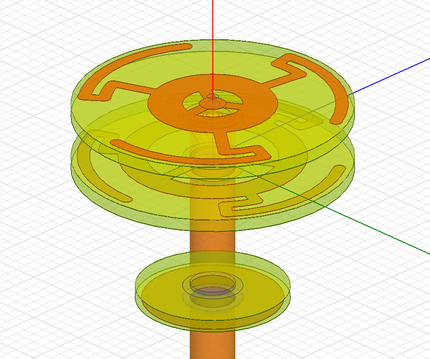
I quickly realized that the easiest and cheapest way to get arbitrary shapes manufactured within fine tolerances is to use regular PCBs. Of course this limits the design to flat shapes, so the real challenge was finding a design with a minimal number of PCBs that would achieve the desired properties. The final design is the result of months of simulation and tuning. I won't claim that this design is perfect, but it does seem to have a smoother radiation pattern and a significantly better axial ratio than most other antennas.
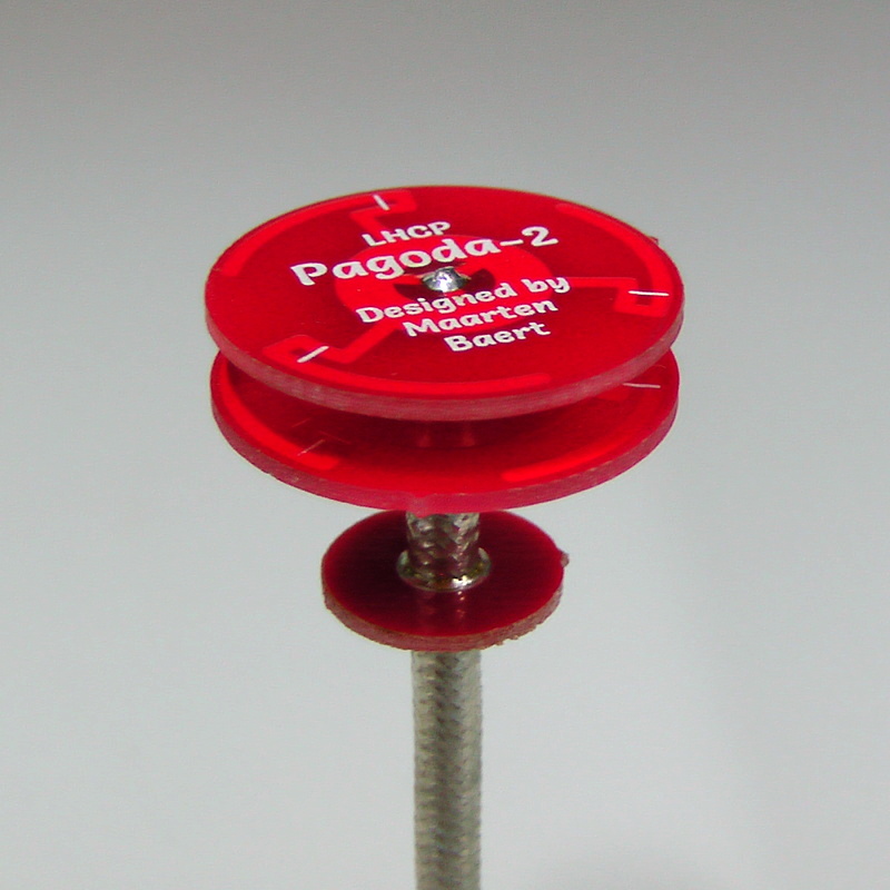
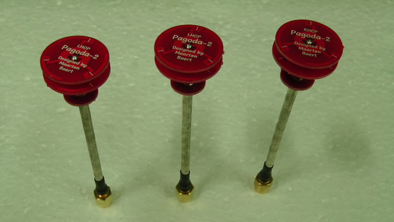
Photo of a Pagoda-2 prototype. The diameter is just 22.5 mm, much smaller than most other designs.
Special thanks to Antenna Test Lab who were kind enough to provide complete spherical anechoic chamber measurements (i.e. 3D radiation patterns) for the Pagoda antenna. You can find a detailed test report of the Pagoda-2 antenna on their website.
Specifications
|
Simulated |
Measured |
Notes | |
|
Center frequency |
5.8 GHz |
5.8 GHz ± 100 MHz |
|
|
Bandwidth |
500 MHz (5.55 – 6.05 GHz) |
500 MHz ± 50 MHz |
|
|
Matching |
S11 < -30 dB, VSWR < 1.065 |
S11 < -20 dB, VSWR < 1.22 |
At center frequency |
|
Axial ratio |
< 1.3 (2.28 dB) |
< 1.33 (2.5 dB) |
Varies with angle and frequency |
|
Antenna gain |
1.2 dBi |
0.0 dBi |
|
|
Radiation efficiency |
94% |
78% |
The center frequency may shift a bit between batches as a result of variations in the dielectric constant of FR4. Also, not all brands of FR4 have the same dielectric constant. Frequency shifts up to 100 MHz are normal.
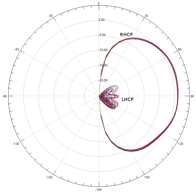
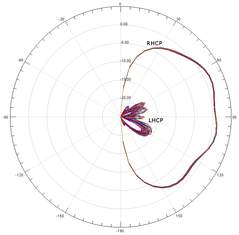
Radiation pattern
|
Simulated (best case, assuming 0% reflection from the feedline) |
Simulated (worst case, assuming 100% reflection from the feedline) |
Measured (anechoic chamber, averaged over full bandwidth) |
|
Simulated 3D radiation pattern (best case). |
Simulated 3D radiation pattern (worst case). |
Measured 3D radiation pattern, by Antenna Test Lab. |
|
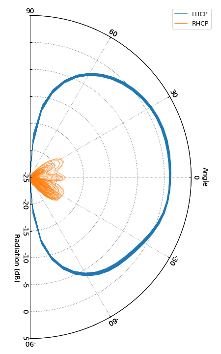
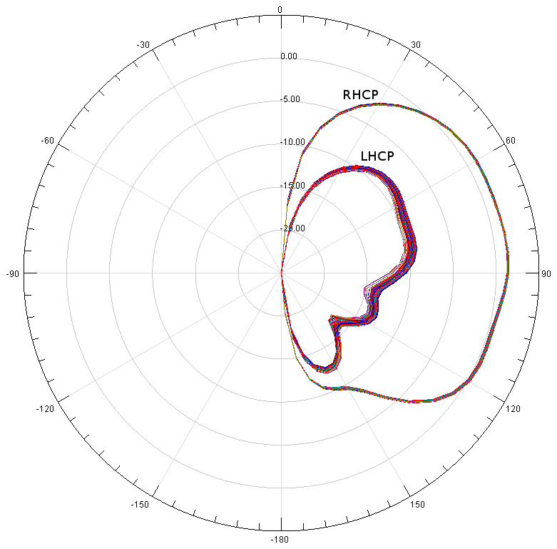
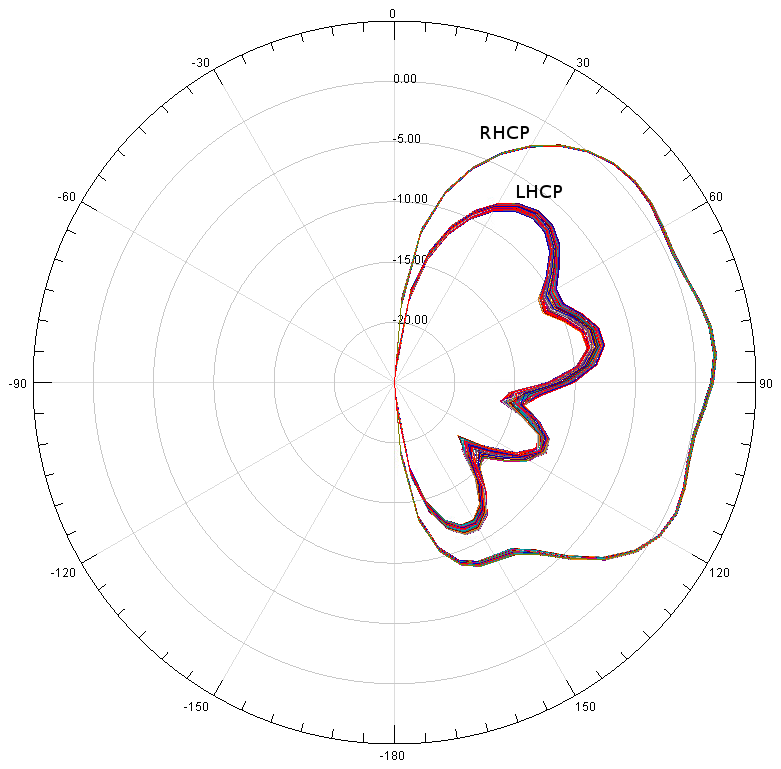
Simulated vertical cross-sections (best case). |
Simulated vertical cross-sections (worst case). |
Measured vertical cross-sections, by Antenna Test Lab. |
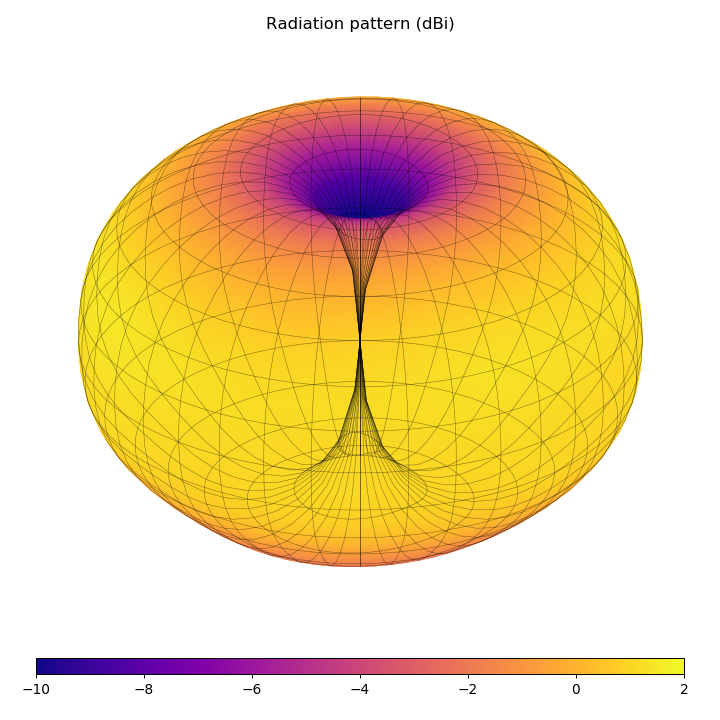

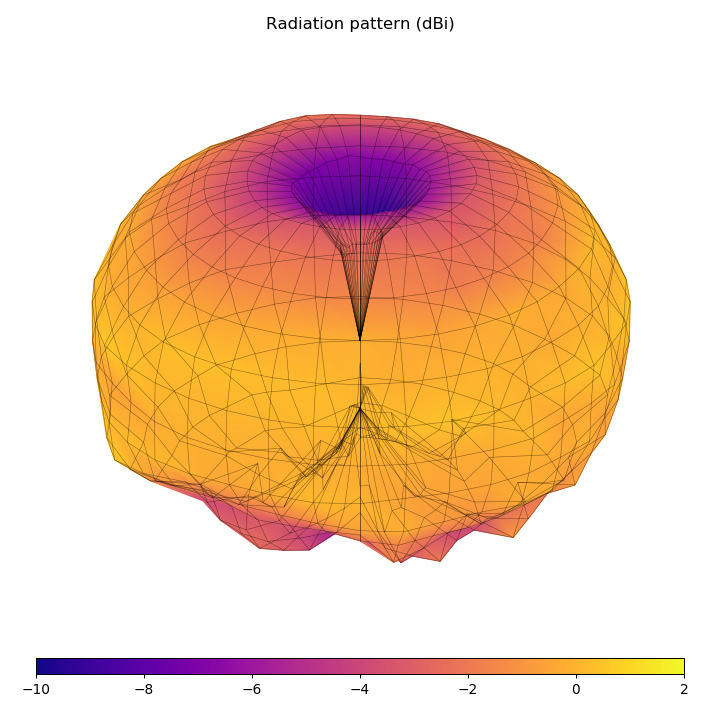
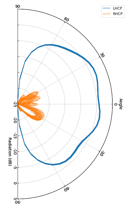

The 'best case' and 'worst case' correspond to different assumptions about what happens to signals that travel along the outside of the coax. In the 'best case' simulation, these are completely absorbed at the other end of the coax. In the 'worst case' simulation, they are completely reflected back towards the antenna. The latter case usually results in standing waves on the outside of the coax, which causes the coax itself to radiate and interfere with the radiation pattern of the antenna. This is why the radiation pattern isn't smooth anymore. The reality will be somewhere between these two extremes.
Note: You are free to use these images for marketing purposes if you are selling Pagoda antennas as long as you link back to this page. Additionally, if you use the images based on the anechoic chamber measurements from Antenna Test Lab, please link back to antennatestlab.com as well.
Animated 3D radiation pattern, by Antenna Test Lab.
For comparison, here's a simulation of the Pagoda antenna and a traditional cloverleaf antenna using the same simulation software and setup:
|
Simulation model. |
Best case, vertical cross-section taken at various angles. |
Worst case, vertical cross-section taken at various angles. |
|
Simulation model. |
Best case, vertical cross-section taken at various angles. |
Worst case, vertical cross-section taken at various angles. |

VNA measurements
|
Prototype units used for measurements, two LHCP and one RHCP. |
VNA measurements. |

This gives you an idea of the kind of variations you can expect for hand-assembled antennas. The center frequency is a bit off but not enough to cause any problems. This is most likely caused by variations in the FR4 material used by the manufacturer.
Some more measurements can be found here.
Where can I buy one?
I have no plans to manufacture these antennas myself, I'm hoping that other antenna builders will pick up this design and start selling it.
The following manufacturers are selling the Pagoda antenna:
|
Manufacturer |
Price* (USD) |
LHCP |
RHCP |
SMA |
RP-SMA |
Notes |
|
$18.00 |
|
|
|
|
Three different lengths available. With plastic (TPU) spacers and shell for improved robustness. No measurements (yet) - performance may differ from my reference design. Longer lengths will likely perform better. | |
|
$6.90 |
|
|
|
|
Long and short version available. With ABS shell for improved robustness. No measurements (yet) - performance may differ from my reference design. Longer lengths will likely perform better. | |
|
$8.99 |
|
|
|
|
Available in multiple colors. PCB thickness and spacing doesn't match my specifications, which may affect the performance. Measurement results here. | |
|
$11.99 |
|
|
|
|
Straight or 90-degree connector available. Also sells ABS and TPU covers, kits and individual PCBs + assembly jig. | |
|
$8.78 |
|
|
|
|
Only ships to the Czech Republic and Slovakia. | |
|
$15 for 2 |
|
|
|
|
50mm or 80mm variant available. Sold by multiple distributors, price may vary slightly. Measurement results here. | |
|
$14.9 for 2 |
|
|
|
|
||
|
$9.99 for 2 |
|
|
|
|
Includes plastic spacers between PCBs, which may affect the performance. Measurement results here. | |
|
$10.07 |
|
|
|
|
Only ships to the Philippines. 50mm or 80mm variant available. | |
|
$12.99 |
|
|
|
|
Straight connector, shorter length. | |
|
$11.40 |
|
|
|
|
With injection moulded protective shell. Measurement results here. | |
|
$7.5 |
|
|
|
|
Straight or 90-degree connector available. | |
|
$7.00 |
|
|
|
|
Every antenna is individually tested with a spectrum analyzer. | |
|
$4.5 - $7 |
|
|
|
|
Price depends on options. | |
|
$14.17 for 2 |
|
|
|
|


* Based on listed price and exchange rate at time of writing. May be outdated. Shipping not included.
If you are a manufacturer who is selling this design, feel free to email me or leave a comment below.
You can also just build them yourself, it's really not that hard. Just download the design files and follow the instructions below.
License

This work is licensed under a Creative Commons Attribution-ShareAlike 4.0 International License.
This means you are free to use this design in any way you like (this includes commercial use) as long as you credit me. If you choose to modify the design files, you should share the modified design files under the same license.
Design files
Pagoda-1
This was the first prototype I ever made. Because of modeling inaccuracies the center frequency was 5.63 GHz instead of 5.8 GHz, which was fixed in the next version. Design files are not available.
Pagoda-2
This version has two variants:
-
2: The default variant, for use with bare PCBs or light foam spacers.
-
2B: This variant was re-tuned for use with plastic shells (specifically the 1mm thick ABS shell used by MenaceRC).
Everything is included in a single zip file: Download
Pagoda-3
This version has two variants just like the Pagoda-2, but this time I generated design files for various center frequencies. The 5.8 GHz Pagoda-3 is identical to the Pagoda-2, I just changed the version number to avoid confusion. Because re-tuning takes a lot of time, I did not re-tune every frequency independently, instead I generated designs for 5.5 GHz and 5.8 GHz, and derived the rest with interpolation/extrapolation. Because of the large file size, I have split the designs into separate zip files this time.
Python scripts used to generate the files: Download
|
Generated design files |
5.3 GHz |
5.4 GHz |
5.5 GHz |
5.6 GHz |
5.7 GHz |
5.8 GHz |
5.9 GHz |
6.0 GHz |
|
PCB for Pagoda-3 |
||||||||
|
PCB for Pagoda-3B |
||||||||
|
Assembly jig for Pagoda-3/3B |
The correct PCB distance is frequency-dependent:
|
Parameter |
5.3 GHz |
5.4 GHz |
5.5 GHz |
5.6 GHz |
5.7 GHz |
5.8 GHz |
5.9 GHz |
6.0 GHz |
|
D1 |
4.39 mm |
4.24 mm |
4.10 mm |
3.95 mm |
3.80 mm |
3.65 mm |
3.51 mm |
3.36 mm |
|
D2 |
11.63 mm |
11.40 mm |
11.16 mm |
10.92 mm |
10.69 mm |
10.45 mm |
10.21 mm |
9.98 mm |
Important: This antenna will only work properly when manufactured and assembled correctly. This is not just a regular circuit board, read the instructions below!
Parts
If you decide to build this antenna, you will need the following parts:
-
PCBs: Manufacturers will make these for you if you send them the Gerber files which are included in the design files above. I used Elecrow for my prototypes, they will make 10 PCBs for $10. That means you end up paying $3 per antenna (it gets much cheaper if you make them in larger quantities). The PCBs must use 1.0 mm thickness FR4 material, not the regular 1.6 mm thickness. The correct thickness is critical, if you get this wrong the design won't work properly at all! Regarding copper thickness, 35 µm (1 oz) is fine. Thicker copper tracks won't improve the efficiency at RF frequencies due to the skin effect. The design is tuned for standard FR4, but there may be small variations between different FR4 manufacturers which can result in a shift in the center frequency of the antenna. I specifically made sure that the design isn't too sensitive to material variations, so this shouldn't be a huge problem, but you should still avoid manufacturers that use special materials with different dielectric constants than regular FR4.
-
Coax: Regular RG402 coax, with a 0.92 mm core, 3.0 mm dielectric, and 3.6 mm outer diameter. Make sure that you use a type that doesn't have a plastic insulator around it, otherwise you can't solder to it. I used this for my prototypes. It costs $5 for 1 meter, and you need 9 cm per antenna, so that's about $0.5 per antenna.
-
SMA connector: Regular solderable SMA connector for RG402 cable. You can also use a crimp connector if you have the right crimp tool. I used this for my prototypes (or if you want RP-SMA, this one). They cost $6 for 10 pieces, so that's $0.6 per antenna. It works fine, but I found that these connectors have a tiny bit too much capacitance (i.e. the impedance is a bit too low), which causes a small but measurable reflection. I also found that the gold plating can wear off if you handle them a lot. This doesn't affect the performance, it just looks ugly. If you can find a better type, let me know.
If you include shipping costs, you will probably pay $50-$60 for the parts to make 10 antennas.
Order configuration for Elecrow
-
Layers: "2"
-
PCB Thickness: "1.0mm"
-
Copper Weight: "1oz 35um"
-
PCB Size: "5cm Max * 5cm Max"
-
PCB Color: "Red" (or anything else, it really doesn't matter)
-
Surface Finish: "Hasl" (or "Hasl (lead free)" if you use lead-free solder)
-
PCB Stencil: "No Stencil"
-
Lead time: your choice
-
Panelizing: "Single PCB with milling"
Order configuration for SeeedStudio
-
Material: "FR-4 TG130"
-
Layers: "2 layers"
-
Dimensions: "50" * "50"
-
PCB Qty: "10"
-
Panelized PCBs: "1"
-
PCB Thickness: "1" mm
-
PCB Color: "Red" (or anything else, it really doesn't matter)
-
Surface Finish: "Hasl" (or "Hasl Lead Free" if you use lead-free solder)
-
Copper Weight: "1oz"
-
Min Hole Size: "0.3mm"
-
Min Tracking / Spacing: "6/6 mil"
-
Blind Vias: "no"
-
Half-cut / Castellated Holes: "no"
-
Impedance Control: "no"
Assembly
The PCBs need to be spaced accurately to get good results. The correct spacing is shown in the following image:
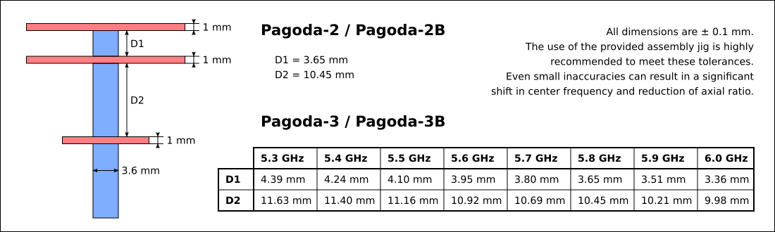
Ideally you need to get these distances right within a 0.1 mm tolerance. The best way to do this is with an assembly jig. I used a jig which I cut out of 3.0 mm MDF with a laser cutter. You can find it in the design files. Always check whether the DXF file is loaded properly by the laser cutter software before you run it, because the DXF export feature in Inkscape is somewhat buggy. Some laser cutters act as printers, in this case it's much more reliable to just 'print' the SVG from Inkscape directly.
Cut out two copies, because these parts aren't very strong so you want to have some spare ones (and MDF is very cheap). If you can't get access to a laser cutter, there are some online services that can make these for you, but I have no experience with those. If that's also not an option, you can also try to get the correct spacing by stacking pieces of wood and paper until you get the correct thickness. You can actually get half-decent accuracy with this method if you measure the thickness with a caliper, but it's not a convenient assembly method. I assembled my first two prototypes like this, it took me at least twice as long as with the assembly jig, and the accuracy was obviously not as good.
The top PCB should have the text facing up, the other two PCBs should have the text facing down. Check my photo if you aren't sure you are doing it right. The top and middle PCB should be aligned using the alignment markers (the three little silkscreen lines that are printed on both sides), otherwise the antenna will not work at all. You can align them easily by rotating the PCBs until the markers are aligned with the edges of the arms of the assembly jig.
A temperature-controlled soldering iron is recommended. Set the temperature to 400 °C, because you need to solder directly to the coax which tends to act as a heat sink. Even with a high temperature it will take some time to heat up the coax, so just be patient. If you don't wait long enough for the coax to heat up, you won't get a decent solder joint. Give the solder enough time to flow into the gap between the PCB and the coax, and rotate the antenna so you can apply heat and solder from all sides. Try to use no more solder than necessary, because excess solder will shift the center frequency of the antenna.
Reviews
-
TBS Triumph vs Pagoda-1, by RCModelReviews.
-
Antenna shootout including Pagoda-2, by Joshua Bardwell.
Extras
-
3D-printed plastic reinforcements, by Lee Schofield (a.k.a. Painless360).
-
STL files for TPU/ABS cover, by FarVew.
-
Alternative 3D-printed assembly jig, by Wuzzle. Probably easier to use than the original if you do not have access to a laser cutter.
-
PCB panels, by Fishpepper. Useful if you want 160 antennas :).
-
Alternative carbon fiber assembly jig + assembly instructions, by Philipp Seidel.
-
Step-by-step guide to ordering, customizing and building Pagoda antennas, by Philipp Seidel.
Frequently asked questions
Can you send me a sample?
I don't have enough prototypes left at the moment, so no. I also have no plans to sell these myself.
Can I fill the space between the PCBs with foam to make the antenna stronger?
Yes, in fact this was the plan all along. I just didn't do it for the prototypes because it takes more effort and they are already pretty strong without it. I recommend low-density Styrofoam (the 30 kg/m³ type). I'm referring to 'real' Styrofoam, which is usually blue, uniform and sold as insulating material. This is not the same as the white expanded polystyrene foam which is commonly used as packaging material, which is often (incorrectly) called 'styrofoam' in the US. They both have similar RF properties and are both suitable, but the white type is made out of little balls which makes it much harder to cut properly, whereas 'real' Styrofoam is uniform and very easy to cut.
These foams are roughly 97% air (by volume) so the dielectric constant is also very close to that of air (roughly 1.05), which means that it has virtually no effect on the performance of the antenna. You could adjust the spacing between the PCBs if you really wanted, but this actually makes the axial ratio slightly worse, so I would just leave it as it is. The addition of foam will shift the center frequency down by about 10 MHz, which isn't a problem. If your really want to get the center frequency just right, you should scale back all dimensions equally, not just the spacing of the PCBs.
Do not try this with higher density foams though, and make sure that the foam doesn't absorb RF radiation (i.e. it should have a very low loss tangent - polystyrene is ideal for this). If you plan to glue the foam to the PCB, you should use a very thin layer of glue. Epoxy should be fine. I haven't tested how much impact this has, but I expect that it won't be a problem.
Feedback, questions, ...
You can leave comments below, or if you prefer you can also email me:

If you don't get a reply within a week, your message was probably eaten by the spam filter. If that happens, try sending the message again from a different address.
Comments
Unclemcpeanut |
Comment #1: Thu, 22 Sep 2016, 13:13 (GMT+1, DST) hi would you be able to consolidate the antennae to a single pcb layout for cheaper pcb prototyping? i believe all 3 pcb components can fit on a 50x50mm pcb, i attempted to do it on viewplot 2.0 but it's a very limited program and im unsure how to merge different layers, k thx bye |
Maarten BaertAdministrator |
Comment #2: Fri, 23 Sep 2016, 3:22 (GMT+1, DST) Quote: Unclemcpeanut
hi would you be able to consolidate the antennae to a single pcb layout for cheaper pcb prototyping? i believe all 3 pcb components can fit on a 50x50mm pcb, i attempted to do it on viewplot 2.0 but it's a very limited program and im unsure how to merge different layers, k thx bye Most prototyping services do not allow this. Elecrow charges extra for panelized prototypes. Seeedstudio charges extra if the parts are different but not if they are identical (but with this antenna they clearly aren't). It ends up being cheaper to order the parts separately. If you want to manufacture a lot of them, then the cheapest option is to order 100x100mm panels of identical parts. But that doesn't really make sense for hobbyists. Last modified: Fri, 23 Sep 2016, 3:24 (GMT+1, DST) |
Btgreg |
Comment #3: Fri, 23 Sep 2016, 9:26 (GMT+1, DST) Hi Maarten, I really like your pagoda design. I too have designed and manufacture antenna's I would like to discuss with you, have you got an email address? Many Thanks |
Maarten BaertAdministrator |
Comment #4: Sat, 24 Sep 2016, 18:13 (GMT+1, DST) Quote: Btgreg
Hi Maarten, I really like your pagoda design. I too have designed and manufacture antenna's I would like to discuss with you, have you got an email address? Many Thanks My email address is displayed on this very page, right above the comments ;). |
Causemann |
Comment #5: Fri, 30 Sep 2016, 20:58 (GMT+1, DST) Hello I woukd like to build thesse antennas. Which program do i need to open them? Best regards |
Maarten BaertAdministrator |
Comment #6: Fri, 30 Sep 2016, 23:23 (GMT+1, DST) Quote: Causemann
Hello I woukd like to build thesse antennas. Which program do i need to open them? Best regards You can open these files with Gerbv. |
Dave855 |
Comment #7: Thu, 27 Oct 2016, 21:33 (GMT+1, DST) Okay I have now completed antennas, assembled kits and just the PCBs for those that have everything else. http://farvew.com/29-pagoda-omni Thanks Maarten! |
Rocketnutz |
Comment #8: Wed, 16 Nov 2016, 22:54 (GMT+1, DST) Just check the link for the store - all out of stock. Hope you can restock soon - would love to give these a go!!! Thanks! |
Dave855 |
Comment #9: Fri, 18 Nov 2016, 23:12 (GMT+1, DST) Indeed, I have a lot more coming. |
Hippo |
Comment #10: Fri, 2 Dec 2016, 5:28 (GMT+1, DST) Hi, Is it possible to calculate the layout for an antenna using standard 1.5/1.6mm PCB? I'd like to make some at home, but I can't find any 1.0mm anywhere. If it's a matter of scaling the file, or running the script with difference values, I can do, but beyond that I'd need an expert. I'm sure a lot of folks would like to make these at home though. Thanks! |
Maarten BaertAdministrator |
Comment #11: Sat, 3 Dec 2016, 20:32 (GMT+1, DST) Quote: Hippo
Hi, Is it possible to calculate the layout for an antenna using standard 1.5/1.6mm PCB? I'd like to make some at home, but I can't find any 1.0mm anywhere. If it's a matter of scaling the file, or running the script with difference values, I can do, but beyond that I'd need an expert. I'm sure a lot of folks would like to make these at home though. Thanks! There is no easy way to scale the values, I would have to re-run the entire optimization process. Also, 1.6mm PCB would increase the losses significantly. I don't recommend it. If you want to go to a lower value instead (e.g. 0.8mm) then that's possible, although it still requires re-optimizing the entire design. |
Hippo |
Comment #12: Sun, 4 Dec 2016, 16:57 (GMT+1, DST) Quote: Maarten Baert
If you want to go to a lower value instead (e.g. 0.8mm) then that's possible, although it still requires re-optimizing the entire design. Ah, thanks. I do have some .5mm, but I worry that it would be too fragile. Don't do extra work on my behalf. I'll continue to see if I can track down some 1.0mm. Do you have a recommended source that ships to the US? Thanks for responding, P.S. Out of curiosity, do you think it would work at all to mill down the unprinted side of 1.6mm to a 1mm thickness? I can do that. Also, I'd be interested in your version 1.0 files, as I usually fly in the lower end of the band, or a recommendation to scale the design into the 5.6gHz-5.7gHz range. Double thanks! |
Maarten BaertAdministrator |
Comment #13: Sun, 4 Dec 2016, 23:04 (GMT+1, DST) Quote: Hippo
Ah, thanks. I do have some .5mm, but I worry that it would be too fragile. Don't do extra work on my behalf. I'll continue to see if I can track down some 1.0mm. Do you have a recommended source that ships to the US? Thanks for responding, P.S. Out of curiosity, do you think it would work at all to mill down the unprinted side of 1.6mm to a 1mm thickness? I can do that. Also, I'd be interested in your version 1.0 files, as I usually fly in the lower end of the band, or a recommendation to scale the design into the 5.6gHz-5.7gHz range. Double thanks! FR4 is a composite material, you can't easily thin it like that without getting loose fibers sticking out everywhere. Also, you need two-sided PCBs in order to get a strong connection to the coax, otherwise the copper will just peel off. It may be more practical to just order the PCBs from Elecrow or a similar service. |
Gorto |
Comment #14: Tue, 6 Dec 2016, 10:31 (GMT+1, DST) Hi Maarten, great antenna design and I have made a bunch of them. Will test them out tomorrow with my friends. Just want to say thank you for sharing your design. Last modified: Tue, 6 Dec 2016, 10:31 (GMT+1, DST) |
Sonic Turbulence |
Comment #15: Thu, 8 Dec 2016, 9:50 (GMT+1, DST) Good Day Maarten, I am also into flying fvp quads and helis...I manufacture pc boards in south africa and would like to know if the holes need to be through hole plated for the antenna to work or could I make them just double sided without plating. Thanking you in advance. Sonic |
Maarten BaertAdministrator |
Comment #16: Thu, 8 Dec 2016, 23:36 (GMT+1, DST) Quote: Sonic Turbulence
Good Day Maarten, I am also into flying fvp quads and helis...I manufacture pc boards in south africa and would like to know if the holes need to be through hole plated for the antenna to work or could I make them just double sided without plating. Thanking you in advance. Sonic Technically it is possible to make them without through-hole plating, but the mechanical strength will be worse. Through-hole plating is definitely recommended. |
Dave855 |
Comment #17: Fri, 16 Dec 2016, 0:08 (GMT+1, DST) Quote: Hippo
Quote: Maarten Baert
If you want to go to a lower value instead (e.g. 0.8mm) then that's possible, although it still requires re-optimizing the entire design. Ah, thanks. I do have some .5mm, but I worry that it would be too fragile. Don't do extra work on my behalf. I'll continue to see if I can track down some 1.0mm. Do you have a recommended source that ships to the US? Thanks for responding, P.S. Out of curiosity, do you think it would work at all to mill down the unprinted side of 1.6mm to a 1mm thickness? I can do that. Also, I'd be interested in your version 1.0 files, as I usually fly in the lower end of the band, or a recommendation to scale the design into the 5.6gHz-5.7gHz range. Double thanks! Hey Dan, Sorry I'm late. Once you go Pagoda you never go back! ;) http://farvew.com/antenna-kits/38-pagoda-2-omni-antenna-rhcp.html Last modified: Fri, 16 Dec 2016, 0:08 (GMT+1, DST) |
Knifa |
Comment #18: Mon, 19 Dec 2016, 13:08 (GMT+1, DST) Hey there! Are you able to post the source files for your design? The ones you provided are the Gerber files and I'm finding it tricky to get them imported into EAGLE. |
Dampf |
Comment #19: Mon, 26 Dec 2016, 11:11 (GMT+1, DST) Hello Maarten. best regards |
Markiempje |
Comment #20: Thu, 29 Dec 2016, 9:55 (GMT+1, DST) Hi Maarten! Great work, just before i order parts. Can i also use more flexible coax cable? say for instance less thick, flexible so i can route this cable the way i want. Is the length of the Coax cable best at 9cm as you stated, or can this be any arbritrary length (not too long) say 100-150mm? thanks in advance! Mark |
Maarten BaertAdministrator |
Comment #21: Thu, 29 Dec 2016, 21:00 (GMT+1, DST) Quote: Knifa
Hey there! Are you able to post the source files for your design? The ones you provided are the Gerber files and I'm finding it tricky to get them imported into EAGLE. The files were generated with Python scripts, which are also included in the design files. There are no other source files. Quote: Dampf
Hello Maarten. best regards These manufacturers won't allow you to put multiple different PCBs on the same board (or they will charge you extra). E.g. with Seeedstudio the best you can do would be: 10 times 4x4 part1: 160 pieces for $10 You're lucky, Seeedstudio recently changed their pricing model so now this is quite affordable. There are structural integrity issues though - the PCBs will need to be attached to each other so the manufacturer can handle them as a single piece, otherwise they refuse this because you're basically making separate PCBs. And even then they may refuse it because of the amount of milling involved. You will have to manually separate the PCBs and file the rough edges. I will look into it, but I'm not sure whether the manufacturer would accept something like this. Quote: Markiempje
Hi Maarten! Great work, just before i order parts. Can i also use more flexible coax cable? say for instance less thick, flexible so i can route this cable the way i want. Is the length of the Coax cable best at 9cm as you stated, or can this be any arbritrary length (not too long) say 100-150mm? thanks in advance! Mark The length doesn't matter as long as the antenna is a reasonable distance away from the quadcopter frame. However the antenna was specifically designed for 3.6mm semi-rigid coax, I wouldn't try it with flexible coax. Even if the diameter is the same, you will likely not be able to solder to it properly, and the PCBs won't stay parallel the way they are supposed to. Nothing stops you from routing semi-rigid coax through your model though. Last modified: Thu, 29 Dec 2016, 21:03 (GMT+1, DST) |
Dampf |
Comment #22: Fri, 30 Dec 2016, 17:18 (GMT+1, DST) Quote
These manufacturers won't allow you to put multiple different PCBs on the same board (or they will charge you extra). E.g. with Seeedstudio the best you can do would be: 10 times 4x4 part1: 160 pieces for $10 You're lucky, Seeedstudio recently changed their pricing model so now this is quite affordable. There are structural integrity issues though - the PCBs will need to be attached to each other so the manufacturer can handle them as a single piece, otherwise they refuse this because you're basically making separate PCBs. And even then they may refuse it because of the amount of milling involved. You will have to manually separate the PCBs and file the rough edges. I will look into it, but I'm not sure whether the manufacturer would accept something like this. Thanks for your reply. |
Maarten BaertAdministrator |
Comment #23: Sat, 31 Dec 2016, 19:21 (GMT+1, DST) Quote: Dampf
Thanks for your reply. Please let me know whether you find a manufacturer that accepts it at a reasonable price. If they do, I will change the design files to take advantage of this. Last modified: Sat, 31 Dec 2016, 19:26 (GMT+1, DST) |
Dmg |
Comment #24: Fri, 6 Jan 2017, 3:01 (GMT+1, DST) Hi, I've got a lot of experience pushing chinese pcb services to the limits, and I have to tell you that they don't explain well what they mean about panelizing and extra cost. They charge you extra if: Anything else gets through just fine, don't even bother asking, just send them the mechanical layer specifying where to cut, make sure that you don't go below 1mm routing tool diameter (better if you stick to >= 2mm) and maybe send them a picture of a 3D render of how the PCB should look like, that's it. I've got a lot of panelized PCB's manufactured that way at no extra cost by elecrow, smart prototyping and such, and they've never complained. I also panelized your pagodas, fitting all 3 PCB's on a single 50x70 board and sent them to elecrow. They're already manufactured and shipped, and I'm waiting for them to arrive. By the way, can I make the coax wire shorter than 9 cm overall? I'd like to have mini pagodas with 5cm cable but I'm not sure if that would affect the performance. Thanks for the awesome design! |
Maarten BaertAdministrator |
Comment #25: Sun, 8 Jan 2017, 2:10 (GMT+1, DST) Quote: Dmg
Hi, I've got a lot of experience pushing chinese pcb services to the limits, and I have to tell you that they don't explain well what they mean about panelizing and extra cost. They charge you extra if: Anything else gets through just fine, don't even bother asking, just send them the mechanical layer specifying where to cut, make sure that you don't go below 1mm routing tool diameter (better if you stick to >= 2mm) and maybe send them a picture of a 3D render of how the PCB should look like, that's it. I've got a lot of panelized PCB's manufactured that way at no extra cost by elecrow, smart prototyping and such, and they've never complained. I also panelized your pagodas, fitting all 3 PCB's on a single 50x70 board and sent them to elecrow. They're already manufactured and shipped, and I'm waiting for them to arrive. By the way, can I make the coax wire shorter than 9 cm overall? I'd like to have mini pagodas with 5cm cable but I'm not sure if that would affect the performance. Thanks for the awesome design! That's good to know! The important thing is the distance between the antenna and the quadcopter frame (or any other large conductive objects). So it really depends on the mounting method. More distance is always better because it reduces the 'dead zones' where your frame is blocking the signal. It depends on how much you value physical size over signal quality I guess. |
Midge |
Comment #26: Sun, 8 Jan 2017, 16:20 (GMT+1, DST) Quote: Dmg
Hi, I've got a lot of experience pushing chinese pcb services to the limits, and I have to tell you that they don't explain well what they mean about panelizing and extra cost. They charge you extra if: Anything else gets through just fine, don't even bother asking, just send them the mechanical layer specifying where to cut, make sure that you don't go below 1mm routing tool diameter (better if you stick to >= 2mm) and maybe send them a picture of a 3D render of how the PCB should look like, that's it. I've got a lot of panelized PCB's manufactured that way at no extra cost by elecrow, smart prototyping and such, and they've never complained. I also panelized your pagodas, fitting all 3 PCB's on a single 50x70 board and sent them to elecrow. They're already manufactured and shipped, and I'm waiting for them to arrive. By the way, can I make the coax wire shorter than 9 cm overall? I'd like to have mini pagodas with 5cm cable but I'm not sure if that would affect the performance. Thanks for the awesome design! Dmg, could you post a link to the file you had manufactured by elecrow? I'm not familiar with pcb or panelizing and would like to make some antennas for myself. |
Dmg |
Comment #27: Tue, 10 Jan 2017, 15:24 (GMT+1, DST) Quote: Midge
Dmg, could you post a link to the file you had manufactured by elecrow? I'm not familiar with pcb or panelizing and would like to make some antennas for myself. Yes, but not yet. I'll wait for the boards to arrive to check if everything is OK, and if it is I'll post the files somewhere. The boards are already in Europe, so I expect them this week. I went the lazy way and panelized them using the Altium Designer gerber importer, and although I checked the resulting panelized gerbers against the original design files and they seemed OK I want to be 100% sure that nothing is messed up (apart from the silkscreen text which got messed but I didn't bother to fix) Also, we've got an anechoic chamber where I work and the guy responsible for it owes me a favor, so he'll measure some pagodas I make when he has some spare time and the chamber isn't being used (i.e someday in the (hopefully near) future). I'll send the results to Maarten when it's done. I really like this design, as me and some friends fly race drones as a hobby and no matter how expensive the antenna we always end up tearing the cable, breaking the antenna, and/or messing them. I don't expect these pagodas to be any tougher in the long term, but they can be made for 2€ a pop or cheaper. That's 10 antennas for the price of one of the ones we use now... and likely with better performance. |
Heribert |
Comment #28: Wed, 11 Jan 2017, 16:48 (GMT+1, DST) Hello, You wrote above that a 0.5mm PCB would be basically possible, actually from a HF point even more beneficial. As I'm interested in flying nano and pico drones, I'm interested in as lightweight antennas as possible. That's why I really would like a 0.5mm PCB design. But I can surely understand that the work you would have to put into to get it optimal is a lot. And how much worse would the performance be without the third GND-PCB? Thanks for your work and that you share it!!! EDIT: EDIT2: Last modified: Sat, 14 Jan 2017, 10:29 (GMT+1, DST) |
Elsvs09 |
Comment #29: Sun, 15 Jan 2017, 14:38 (GMT+1, DST) Hi Maarten, Can we design this antenna for 2.4 GHz? I guess scales of the antenna would be bigger than 5.8 GHz, but the point is how big. Are the proportions scaled to operation wavelength? Thanks in advance. |
Maarten BaertAdministrator |
Comment #30: Mon, 16 Jan 2017, 4:09 (GMT+1, DST) Quote: Heribert
But I can surely understand that the work you would have to put into to get it optimal is a lot. Yes, halve the width of the ring-shaped pad that solders to the coax, and increase the spacing between the PCBs by 0.5mm to compensate of the change in thickness. This will probably shift the frequency up a bit, so scale up the arms about 5% to shift the frequency down again. I'm just guessing here so don't be surprised if the result performs poorly. Quote: Heribert
And how much worse would the performance be without the third GND-PCB? You will lose some of the power as it is propagating along the coax. The result depends on how the coax attaches to the TX, the shape of the TX etc, so basically impossible to predict. I don't recommend it. Quote: Heribert
BTW, how much would the performance be affected if one would route away the non copper parts of the PCB? (this could also decrease the weight signigicantly.) It's all fixable with sufficient re-optimization but this takes a lot of time. If you want to reduce weight, your biggest target should probably be the RG402 coax. Thinner coax is probably better for your application. Quote: Heribert
Would it eventually be possible for you to publish your NEC simulation file? I do not use NEC. NEC is pretty much worthless for these types of antennas at this frequency. The results are just completely off. You need something like HFSS or CST (but those are both far too expensive for hobbyists, so you need to be a student at a university or something to get a chance to use it). Quote: Elsvs09
Can we design this antenna for 2.4 GHz? I guess scales of the antenna would be bigger than 5.8 GHz, but the point is how big. Are the proportions scaled to operation wavelength? Thanks in advance. Roughly speaking, yes, but in practice not everything is easy to scale. The PCB and coax would become too thick, so you probably don't want to scale those. I would have to re-optimize the design. Also, at 2.4 GHz the size is about 53mm which is a bit impractical. Cloverleafs may be a better option at that frequency. Last modified: Mon, 16 Jan 2017, 4:12 (GMT+1, DST) |
Dmg |
Comment #31: Tue, 17 Jan 2017, 22:07 (GMT+1, DST) Quote: Midge
Dmg, could you post a link to the file you had manufactured by elecrow? I'm not familiar with pcb or panelizing and would like to make some antennas for myself. Here, I just posted them: Boards arrived, I've assembled one today, so far looks good. About 500 MHz bandwidth (-10 dB return loss) with a resonant frequency of 5,83 GHz (RL peaks at -35 dB). We'll see how the radiation pattern turns out. |
Serop72 |
Comment #32: Sun, 29 Jan 2017, 21:08 (GMT+1, DST) Hello!in figure assembly distance between the layers of 3.65mm and 10.45mm It is right? Thank you for your work! very interesting design, I'm going to do the antenna |
Stinkyjohn |
Comment #33: Fri, 3 Feb 2017, 10:03 (GMT+1, DST) Hi to all, And one more thing, beware printed cases for Pagodas. I've printed them from PLA, PLA+, TPU, ABS, PETG and TITANX. Anyway, great design. When weather will allow, we will test them on our racing field. |
Maarten BaertAdministrator |
Comment #34: Sat, 4 Feb 2017, 21:22 (GMT+1, DST) Quote: Serop72
Hello!in figure assembly distance between the layers of 3.65mm and 10.45mm It is right? Thank you for your work! very interesting design, I'm going to do the antenna The correct numbers are 3.65mm and 10.45mm. The laser cutting drawing was adjusted to compensate for the line width of the laser, which is roughly 0.2mm (at least for the model that I'm using). If the slots are too narrow, you can easily widen them with some fine sandpaper or a small file. If they are too wide, they don't hold the PCB in place very well which is annoying. They also widen automatically as you use them because the jig wears out over time. Quote: Stinkyjohn
Hi to all, This is strange, I can get much better repeatability myself and I'm also using manual assembly. The 'VNA measurement' graph above shows three units which I assembled manually, I was seeing only about 50 MHz variation. I have found that the solder joints matter a lot. Make sure that you are using the right amount of solder and heating the joints long enough to ensure they reflow properly (like I do in my assembly video). Quote: Stinkyjohn
I've also noted that connector type and manufacture of cable will also have impact on antenna. Yes, I have noticed that too. The length of the cable also has some impact because it affects the phase shift between the SMA connector and the antenna. If the connector was perfect, this would not matter, but the fact that I can measure a difference indicates that the SMA connector I'm using isn't perfect. Quote: Stinkyjohn
And one more thing, beware printed cases for Pagodas. I've printed them from PLA, PLA+, TPU, ABS, PETG and TITANX. I know - if you want a case, you should consider scaling the antenna down to compensate for the frequency shift. But if the case is thin enough, the shift is quite small, so the antenna will still work quite well. I have done measurements of the MenaceRC model with case, and it was only shifted down by about 100 MHz. |
Peter62233460 |
Comment #35: Sun, 5 Feb 2017, 20:47 (GMT+1, DST) Hi Marteen! Thanks for designing this awesome antenna. I would like to build the antenna and I was wondering whether I could use other coaxes instead of the RG402 you recommend. I bought some RG316 cables years ago and I am wondering whether this would be okay to use. As for the construction jig, I can modify the design to accept the narrower cable and laser cut it. Thanks, Peter. |
Pauloxzr |
Comment #36: Thu, 16 Feb 2017, 7:08 (GMT+1, DST) Hello Maarten Baert! Greetings from Brazil! My name is Paul! First of all I want to congratulate you for your brilliant work! I've always wanted to make my own antennas and with your project I see that I have the opportunity to make my first antenna correctly and accurately. I have spent a lot of money buying antennas that are not efficient and resistant, and I found in your project what I need. In the city and country where I live I do not have many resources, like a company that makes PCBs. I have only people who have machines that do the cutting and drawing of PCBs, but these machines only receive source files made in pcad, orcad, proteus, eagle. Is there any way to convert Gerber files to be interpreted on these machines and programs? I am very interested in your project! I do not want to make antennas for resale or make money, I just want it for personal use in my racing drone. I have an intermediate experience in electronics, and I can build the antennas precisely as described in the videos I saw on your site. The only detail is that I do not have the machine to cut the PCBs. Thank you very much for what you can do for me. Thank you very much. |
Gadgetfpv |
Comment #37: Fri, 17 Feb 2017, 16:04 (GMT+1, DST) Hi.. Thank you for sharing this design... can't wait to try... one quick question... the smaller disc in the assembly has copper in it, correct... Sorry if this a simple question, quite new to all of this PCB design stuff... Gadget |
Luno |
Comment #38: Fri, 17 Feb 2017, 22:19 (GMT+1, DST) Hi! I've got a Beerotor Honeydrop antenna which is using your Pagoda design. The cable shielding is missing between the top and the middle PCBs. I wonder if this antenna performs bad because of that. http://forum.rcdesign.ru/attachment.php?attachmentid=1298680&d=1487348602 |
Nhillerby |
Comment #39: Mon, 20 Feb 2017, 2:23 (GMT+1, DST) Hello Maarten, could this sma cord included in the pagoda 2 kit be cut down to a shorter length? It's a bit lengthy for fpv. Thank you for your genious invention. |
Maarten BaertAdministrator |
Comment #40: Tue, 21 Feb 2017, 1:40 (GMT+1, DST) Quote: Peter62233460
Hi Marteen! Thanks for designing this awesome antenna. I would like to build the antenna and I was wondering whether I could use other coaxes instead of the RG402 you recommend. I bought some RG316 cables years ago and I am wondering whether this would be okay to use. As for the construction jig, I can modify the design to accept the narrower cable and laser cut it. Thanks, Peter. The design is made for RG402 and won't perform properly with cables that have a different diameter. It requires re-optimization of the design. I don't have time to do that now though. Also, RG316 is likely too flexible for this antenna. Quote: Pauloxzr
Hello Maarten Baert! Greetings from Brazil! My name is Paul! First of all I want to congratulate you for your brilliant work! I've always wanted to make my own antennas and with your project I see that I have the opportunity to make my first antenna correctly and accurately. I have spent a lot of money buying antennas that are not efficient and resistant, and I found in your project what I need. In the city and country where I live I do not have many resources, like a company that makes PCBs. I have only people who have machines that do the cutting and drawing of PCBs, but these machines only receive source files made in pcad, orcad, proteus, eagle. Is there any way to convert Gerber files to be interpreted on these machines and programs? I am very interested in your project! I do not want to make antennas for resale or make money, I just want it for personal use in my racing drone. I have an intermediate experience in electronics, and I can build the antennas precisely as described in the videos I saw on your site. The only detail is that I do not have the machine to cut the PCBs. Thank you very much for what you can do for me. Thank you very much. I sent you DXF files by email, try to use those. Gerber files are still the recommended format though, it's the industry standard for PCB design. I've never heard of any manufacturer that can't accept Gerber files. Quote: Gadgetfpv
Hi.. Thank you for sharing this design... can't wait to try... one quick question... the smaller disc in the assembly has copper in it, correct... Sorry if this a simple question, quite new to all of this PCB design stuff... Gadget Yes, the bottom side of the small disk is almost entirely covered with copper. Quote: Luno
Hi! I've got a Beerotor Honeydrop antenna which is using your Pagoda design. The cable shielding is missing between the top and the middle PCBs. I wonder if this antenna performs bad because of that. http://forum.rcdesign.ru/attachment.php?attachmentid=1298680&d=1487348602 I have seem many people complain about build quality issues with that antenna. Problems with the SMA connector, bad PCB alignment, cases that fall apart, bad soldering and so on. I don't recommend it. Quote: Nhillerby
Hello Maarten, could this sma cord included in the pagoda 2 kit be cut down to a shorter length? It's a bit lengthy for fpv. Thank you for your genious invention. You can shorten it, but this will bring the antenna closer to the quadcopter frame which will result in a larger 'dead zone' where the frame is blocking the signal. Just be aware of that. |
Gadgetfpv |
Comment #41: Tue, 21 Feb 2017, 10:31 (GMT+1, DST) Dear Maarten, Thank you so much for responding to my last post... Now my PCB supplier is asking whether the PCB is Single or Double Sided? Would you be kind enough to let me know... Last modified: Tue, 21 Feb 2017, 10:42 (GMT+1, DST) |
Willem |
Comment #42: Thu, 23 Feb 2017, 14:52 (GMT+1, DST) Dag Maarten, waar kan ik de kits voor deze antennes kopen in België aub? |
Tok |
Comment #43: Thu, 23 Feb 2017, 20:46 (GMT+1, DST) Hi Marteen Are there any plans for a 1280Mhz version of the pagoda ? Br |
Matan |
Comment #44: Fri, 24 Feb 2017, 10:35 (GMT+1, DST) Hi. I think it's because of a minor mistake on the gap between the PCBs, they are about 0.1-0.2mm closer then what you specified. I intend to design a new jig that will make the assembly more convenient, as well as more accurate. (and will that will be 3d printed and not laser cut, which is where my inaccuracy come from) So, do you think its possible to cut a notch in the two big PCBs so they will be at a fixed position in the jig? (instead of the silkscreen lines, cut three tiny notches on the outer part of the PCB and have a dimple in the jig that will sit in the notch so they will be at fixed position to one another) Will it have an impact on the performance? Thanks, |
Ivan |
Comment #45: Sun, 26 Feb 2017, 15:10 (GMT+1, DST) Thanks for your antenna design Maarten. ps. got 2 pagoda antennas in meantime to play with from Menace. SWR seems better without the protection cover. Last modified: Sun, 26 Feb 2017, 19:17 (GMT+1, DST) |
Willem |
Comment #46: Wed, 1 Mar 2017, 15:47 (GMT+1, DST) Hi Maarten, where can I buy these antenna kit(s) in Belgium please? |
Rotordog |
Comment #47: Sun, 12 Mar 2017, 21:23 (GMT+1, DST) I was wonder what makes the difference in a RHCP and LHCP with the Pagoda? Are the templates in the disc simply going in the opposite direction to change the polarization> Like a cloverleaf. I also thought I understood from previous post that in fact the cable length creates no no issues so long as the disc do not contact anything potentially conductive. Thanks! |
Rotordog |
Comment #48: Sun, 12 Mar 2017, 21:54 (GMT+1, DST) One last question. Would it cause any issue with performance if you dipped the PCB antenna disc and at least part of the coax in a protective liquid vinyl? |
Efeksk |
Comment #49: Mon, 13 Mar 2017, 14:34 (GMT+1, DST) Hello maarten I need help on a topic. I also want to make a small donation for you. [img]http://i.hizliresim.com/ZZ7WYo.jpg[/img] |
Maarten BaertAdministrator |
Comment #50: Sun, 19 Mar 2017, 16:22 (GMT+1, DST) Quote: Gadgetfpv
Now my PCB supplier is asking whether the PCB is Single or Double Sided? Would you be kind enough to let me know... Double sided, otherwise you will miss some pads on the bottom side and you won't get through-hole metallization. Quote: Tok
Are there any plans for a 1280Mhz version of the pagoda ? No, it would be too big to be practical. Quote: Matan
I built the antennas, and I'm having some performance problems. I think it's because of a minor mistake on the gap between the PCBs, they are about 0.1-0.2mm closer then what you specified. I intend to design a new jig that will make the assembly more convenient, as well as more accurate. (and will that will be 3d printed and not laser cut, which is where my inaccuracy come from) So, do you think its possible to cut a notch in the two big PCBs so they will be at a fixed position in the jig? (instead of the silkscreen lines, cut three tiny notches on the outer part of the PCB and have a dimple in the jig that will sit in the notch so they will be at fixed position to one another) Will it have an impact on the performance? If you place the notches far enough away from the copper elements, it should be fine. You can change the PCBs by modifying the Python scripts that I use to generate them. They are included in the design files. Quote: Ivan
Thanks for your antenna design Maarten. ps. got 2 pagoda antennas in meantime to play with from Menace. SWR seems better without the protection cover. DXF files are now included in the design files. Getting DXF files from Gerbers is really annoying, I generated them from SVGs instead. Quote: Willem
Hi Maarten, where can I buy these antenna kit(s) in Belgium please? I'm not aware of any sellers in Belgium specifically, but I'm pretty sure that you can get the international sellers to ship it to Belgium. Quote: Rotordog
I was wonder what makes the difference in a RHCP and LHCP with the Pagoda? Are the templates in the disc simply going in the opposite direction to change the polarization> Like a cloverleaf. I also thought I understood from previous post that in fact the cable length creates no no issues so long as the disc do not contact anything potentially conductive. Thanks! Yes, the LHCP and RHCP version are just mirror images of each other. Just mirror the two top PCBs and you will get the opposite polarization. Quote: Rotordog
One last question. Would it cause any issue with performance if you dipped the PCB antenna disc and at least part of the coax in a protective liquid vinyl? Yes, unless it's an extremely thin layer (less than 0.1 mm). You can probably get much better results with Styrofoam, which doesn't affect the performance significantly. Quote: Efeksk
Hello maarten I need help on a topic. I also want to make a small donation for you. The Gerber files are generated by Python scripts which are also included in the design files. I did not use traditional PCB software to design these PCBs. |
Goose |
Comment #51: Tue, 21 Mar 2017, 16:47 (GMT+1, DST) Maarten, Two questions as this is the first time I have toyed around with PCB antennas. 1. I am trying to have the PCB's done by a friend of mine here in the US and he is stating that the drill file is not included in the Gerber files. Do you know what he is talking about? If so how would I go about getting those from you? Email? 2. The FR4 needing to be 1mm is only the FR4 correct or is it the overall thickness including the Screenprint? I know the issues with dielectric speed, but you don't provide a total thickness of the board and screenprinting. Thanks. |
Maarten BaertAdministrator |
Comment #52: Wed, 22 Mar 2017, 2:58 (GMT+1, DST) Quote: Goose
Maarten, Two questions as this is the first time I have toyed around with PCB antennas. 1. I am trying to have the PCB's done by a friend of mine here in the US and he is stating that the drill file is not included in the Gerber files. Do you know what he is talking about? If so how would I go about getting those from you? Email? 2. The FR4 needing to be 1mm is only the FR4 correct or is it the overall thickness including the Screenprint? I know the issues with dielectric speed, but you don't provide a total thickness of the board and screenprinting. Thanks. 1. Tell him that the .txt file is the drill file. He probably wants to rename it to some other extension like ".drl". Sadly there's no universal standard for these extensions, some manufacters want ".txt.", others want ".drl" (short for Drill) and yet others want ".xln" (short for Excellon). 2. The 1.0 mm thickness is the base FR-4 material. But realistically it doesn't matter if it's off by a tiny amount, the properties of FR-4 tends to vary between manufacturers anyway. Solder mask is only ~20 µm so I just ignore it, it has no meaningful impact. Last modified: Wed, 22 Mar 2017, 3:00 (GMT+1, DST) |
Dmg |
Comment #53: Sat, 25 Mar 2017, 23:31 (GMT+1, DST) Recently a friend of mine sent his first attempt at PCB panelizing to elecrow. He sent something that no sane PCB manufacturer would make and surprisingly he got exaclty what he ordered with zero compliants and no extra cost. It was a very unstable panel with features we all thought were forbidden in chinese manufacturers. So, now knowing that elecrow will make almost anything, I've decided to design this: I've called it "Pagoda Value Pack" and it includes 3 copies of the Pagoda Antena PCB's (RHCP for now but changing to LHCP is trivial and will do it if this works) with added breakaway alignment struts, a modified simplified assembly jig that uses the alignment struts, an end ruler to measure the coax, a stripping depth gauge for the RP-SMA connector and a template for cutting styrofoam half discs to fill the pagodas. All of that in a single 10x10 cm PCB. I've ordered an experimental batch to see how all works. Hopefully this will simplify the pagoda-making process. We're also testing styrofoam-filled pagodas with very promising results durability-wise! |
Dmg |
Comment #54: Sat, 25 Mar 2017, 23:36 (GMT+1, DST) By the way, I've noticed something strange. Your 3D rendering from the simulator shows that the center PCB has the copper on the bottom side, while the gerbers and assembled pagodas have the center PCB copper on the top side. Is this normal? EDIT: FAIL, I got fooled by the perspective of te 3D rendering. All is OK. Please ingore this comment. Last modified: Sat, 25 Mar 2017, 23:40 (GMT+1, DST) |
Maarten BaertAdministrator |
Comment #55: Mon, 27 Mar 2017, 3:35 (GMT+1, DST) Quote: Dmg
By the way, I've noticed something strange. Your 3D rendering from the simulator shows that the center PCB has the copper on the bottom side, while the gerbers and assembled pagodas have the center PCB copper on the top side. Is this normal? EDIT: FAIL, I got fooled by the perspective of te 3D rendering. All is OK. Please ingore this comment. Yeah, the 3D viewer has half-broken transparency support. It doesn't know which parts should be drawn in front and in many cases it messes up. You don't get that problem with opaque colors, but then you can't really see what you're doing. I've learned to ignore it :). |
Tripd27 |
Comment #56: Tue, 28 Mar 2017, 21:36 (GMT+1, DST) I noticed in your ReadMe file when ordering from Elecrow to select the 1.6mm PCB Thickness, but in your instructions on the page you are very adamant about using 1.0mm PCB. I did order the 1.0mm, just thought I would point this out so you can update your documentation. Great work on the Pagoda Antenna, and thank you for sharing the plans. |
Maarten BaertAdministrator |
Comment #57: Thu, 30 Mar 2017, 4:11 (GMT+1, DST) Quote: Tripd27
I noticed in your ReadMe file when ordering from Elecrow to select the 1.6mm PCB Thickness, but in your instructions on the page you are very adamant about using 1.0mm PCB. I did order the 1.0mm, just thought I would point this out so you can update your documentation. Great work on the Pagoda Antenna, and thank you for sharing the plans. Oops, looks like I somehow copied the default Elecrow settings instead of the edited ones. Thanks for telling me! |
Efeksk |
Comment #58: Mon, 3 Apr 2017, 10:29 (GMT+1, DST) Hello there. |
Andygetfpv |
Comment #59: Tue, 4 Apr 2017, 20:35 (GMT+1, DST) Hi Maarten, I wanted to let you know that Lumenier is now manufacturing the Pagoda antenna in RHCP and LHCP version now. (RPSMA coming soon as well) It would be great if you could link it on the "Where to buy" section. Thanks for all your work on this project! http://www.getfpv.com/lumenier-pagoda-2-5-8ghz-antenna-rhcp.html |
Miki |
Comment #60: Thu, 6 Apr 2017, 18:58 (GMT+1, DST) Hi Maarten, If I use 0.8mm pcb what the distance between the discs should be? |
Unclemcpeanut |
Comment #61: Mon, 10 Apr 2017, 5:17 (GMT+1, DST) hi, i'm attempting to edit the python files but when i run it it send an error, No module named 'pylab', im pretty new to coding and have only done matlab stuff, what do i need to do to get it to work? i have got ipython from the anaconda suite but have no idea where to start. thanks and love your antenna works great on my quad |
Gryphon |
Comment #62: Tue, 11 Apr 2017, 9:11 (GMT+1, DST) Dear Maarten baert, thank you for designing this pagoda antenna . I looking forward to hearing from you Sincerely Gryphon |
Ea7dwk |
Comment #63: Tue, 11 Apr 2017, 21:14 (GMT+1, DST) Hi MAARTEN : thanks a lot for your "pagoda" antenna.- So a great and lovely job !!.- I´m wondering myself about the thinner RG405 coax cable for RG402 replacement.- Maybe it makes not so much difference.- 73,s. |
Maarten BaertAdministrator |
Comment #64: Sat, 15 Apr 2017, 4:10 (GMT+1, DST) Quote: Efeksk
Hello there. You can do this by editing the Python script that generates the files. Quote: Andygetfpv
Hi Maarten, I wanted to let you know that Lumenier is now manufacturing the Pagoda antenna in RHCP and LHCP version now. (RPSMA coming soon as well) It would be great if you could link it on the "Where to buy" section. Thanks for all your work on this project! http://www.getfpv.com/lumenier-pagoda-2-5-8ghz-antenna-rhcp.html Thanks, added. Quote: Miki
Hi Maarten, If I use 0.8mm pcb what the distance between the discs should be? It's not that simple. If you want to get it exactly right, you need to re-tune the entire design. It's easier to just stick with 1mm. If you really want to try it with 0.8mm, then just keep the distance the same. Quote: Unclemcpeanut
hi, i'm attempting to edit the python files but when i run it it send an error, No module named 'pylab', im pretty new to coding and have only done matlab stuff, what do i need to do to get it to work? i have got ipython from the anaconda suite but have no idea where to start. thanks and love your antenna works great on my quad You need to install a number of modules. 'pylab' is a collection of modules including numpy, scipy and matplotlib. You will also need 'freetype-py'. I have never tried installing it on Windows, but on Linux you can get all of these from the package manager. You can also install them with 'pip' if you are familiar with that. Note that you need python 3, not python 2. Quote: Gryphon
Dear Maarten baert, thank you for designing this pagoda antenna . I looking forward to hearing from you Sincerely Gryphon I have sent you an email. Quote: Ea7dwk
Hi MAARTEN : thanks a lot for your "pagoda" antenna.- So a great and lovely job !!.- I´m wondering myself about the thinner RG405 coax cable for RG402 replacement.- Maybe it makes not so much difference.- 73,s. It is certainly possible, but it would require re-tuning for optimal performance. It would also make the antenna more fragile. |
Prx |
Comment #65: Sun, 23 Apr 2017, 9:20 (GMT+1, DST) Tried sending the ValuePack panel through Elecrow standard service a few days ago and they said they can't manufacture it like this unless I pay $36 instead of the normal $10. Anyone else had any success recently? |
Ps915 |
Comment #66: Fri, 28 Apr 2017, 0:25 (GMT+1, DST) Hi Maarten, first of all thanks for your awesome antenna design. Me and the german FPV Community really like your design. I just wanted to share my personal Pagoda project with the german community with you. i wrote some blogposts about the Pagoda antenna and also translated it for the englisch users. We also created a new soldering aid for cables with already soldered SMA connectors. Assembly: http://blog.seidel-philipp.de/pagoda-fpv-antenna-assembly/ Again many many thanks for the work you did. PHIL PS: We are about to test some other flexible calbles to fit some UFL connectors to it. maybe loweering the diameter of the PCB holes and fit some RG316 cables inside. For GND you just ripp of the isolation. What do you think? |
Maarten BaertAdministrator |
Comment #67: Mon, 1 May 2017, 13:03 (GMT+1, DST) Quote: Prx
Tried sending the ValuePack panel through Elecrow standard service a few days ago and they said they can't manufacture it like this unless I pay $36 instead of the normal $10. Anyone else had any success recently? This is normal, Elecrow does not offer free panelization, unlike Seeedstudio. Seeedstudio only allows it when the PCBs are all identical (which is the case here). Quote: Ps915
Hi Maarten, first of all thanks for your awesome antenna design. Me and the german FPV Community really like your design. I just wanted to share my personal Pagoda project with the german community with you. i wrote some blogposts about the Pagoda antenna and also translated it for the englisch users. We also created a new soldering aid for cables with already soldered SMA connectors. Assembly: http://blog.seidel-philipp.de/pagoda-fpv-antenna-assembly/ Again many many thanks for the work you did. PHIL Added. That production error is interesting, I haven't seen that happen before. I guess it's not surprising, concentric pads isn't something you would find on a regular PCB, and the way it gets encoded in the Gerber file is a bit unusual. Quote: Ps915
PS: We are about to test some other flexible calbles to fit some UFL connectors to it. maybe loweering the diameter of the PCB holes and fit some RG316 cables inside. For GND you just ripp of the isolation. What do you think? The coax is part of the 'active' elements of the antenna, so if you change the diameter, you will likely see significant changes in performance. I don't think this will work well without serious re-tuning of the design. |
Ps915 |
Comment #68: Wed, 3 May 2017, 16:55 (GMT+1, DST) Hey guys, Since Seetstudio still sends e-mails that the they did it correctly, i investigated into this. When they produce your boards wrong, this is not your fault. The files are correct. The chinese manufacturer just mixed up the files. There is always only PART 1 (the top PCB), which is produced wrong, because they mixed the bottom layer of PART2 with PART1.I send Seeedstudio the following picture, to hope they understand. Last modified: Wed, 3 May 2017, 16:56 (GMT+1, DST) |
Maarten BaertAdministrator |
Comment #69: Wed, 3 May 2017, 20:59 (GMT+1, DST) Quote: Ps915
Hey guys, Since Seetstudio still sends e-mails that the they did it correctly, i investigated into this. When they produce your boards wrong, this is not your fault. The files are correct. The chinese manufacturer just mixed up the files. There is always only PART 1 (the top PCB), which is produced wrong, because they mixed the bottom layer of PART2 with PART1.I send Seeedstudio the following picture, to hope they understand. That's also possible, but I think it's more likely that their software doesn't properly support the way I'm defining concentric pads in the Gerber file, and deletes the gap between the two pads since the software doesn't understand that there can be two pads in the exact same location and yet not connected to each other. |
Anon1337 |
Comment #70: Mon, 15 May 2017, 19:47 (GMT+1, DST) Hello, farvew.com sells a pagoda 2 antenna labeled as 'Revision B'. Did Maarten create a Revision B or is this their own design? If it is their own design are the design files available? |
Ps915 |
Comment #71: Tue, 16 May 2017, 12:12 (GMT+1, DST) Hey Maarten, what about the length of the coax cable (from sma to the third pcb)? if i want to build a very short antenne, can i do this without problems? Am i right, that after the third PCB the length doesn't matter? |
Auleefor |
Comment #72: Wed, 17 May 2017, 16:26 (GMT+1, DST) Excellent design, I like it very much ! A question please: Did you consider pcb thickness regarding distances between discs ? Thanks for sharing all this knowledge ! |
Maarten BaertAdministrator |
Comment #73: Thu, 18 May 2017, 23:22 (GMT+1, DST) Quote: Anon1337
Hello, farvew.com sells a pagoda 2 antenna labeled as 'Revision B'. Did Maarten create a Revision B or is this their own design? If it is their own design are the design files available? Version '2B' was also created by me, and is included in the latest design files. It is identical to version '2' but re-tuned for antennas with a plastic shell. Quote: Ps915
Hey Maarten, what about the length of the coax cable (from sma to the third pcb)? if i want to build a very short antenne, can i do this without problems? Am i right, that after the third PCB the length doesn't matter? This has been asked many times, see previous comments. Quote: Auleefor
Excellent design, I like it very much ! A question please: Did you consider pcb thickness regarding distances between discs ? Thanks for sharing all this knowledge ! The distance shown in this article is the distance between the PCBs (i.e. FR4), which are supposed to be 1mm thick. If you are using the provided assemby jig, you don't have to worry about this. |
Iforge |
Comment #74: Sun, 21 May 2017, 4:55 (GMT+1, DST) Hi Maarten, Will you be releasing the Rev. B of the antenna? Regards, |
Maarten BaertAdministrator |
Comment #75: Wed, 24 May 2017, 2:30 (GMT+1, DST) Quote: Iforge
Hi Maarten, Will you be releasing the Rev. B of the antenna? Regards, What do you mean? It is already included in the latest design files. |
Iforge |
Comment #76: Thu, 25 May 2017, 10:01 (GMT+1, DST) Oh wow thanks Maarten! I thought it was a different one. Thank you so much! |
Stylesuxx |
Comment #77: Sun, 4 Jun 2017, 3:02 (GMT+1, DST) Quote: Maarten Baert
Version '2B' was also created by me, and is included in the latest design files. It is identical to version '2' but re-tuned for antennas with a plastic shell. I was wondering, is version 2B the recommended version, or is it just recommended if you want to use a plastic shell? Thank you Maarten, for this great design! Last modified: Mon, 5 Jun 2017, 20:47 (GMT+1, DST) |
Maarten BaertAdministrator |
Comment #78: Mon, 5 Jun 2017, 0:01 (GMT+1, DST) Quote: Stylesuxx
I was wondering, is version 2B the recommended version, or is it just recommended if you want to use a plastic shell? Thank you Maarten, for this great design! Only if you use a plastic shell or heat shrink. If you use it unprotected or with just a styrofoam filler, the default version is better. Last modified: Mon, 5 Jun 2017, 20:46 (GMT+1, DST) |
Stylesuxx |
Comment #79: Mon, 5 Jun 2017, 4:36 (GMT+1, DST) Quote: Maarten Baert
Only if you use a plastic shell or heat shrink. If you use it unprotected or with just a styrofoam filler, the default version is better. OK, thank you for the quick reply. I am planning on using 3D printed spacers and heat shrink, so I will go with version 2B. Last modified: Mon, 5 Jun 2017, 20:46 (GMT+1, DST) |
Eosbandi |
Comment #80: Tue, 6 Jun 2017, 23:40 (GMT+1, DST) Hi Marteen, Quick question, i need to retune the antenna for 4.8Ghz (4.8-4.9 band). Could it be done by simply changing the distance between the plates, or I have to resize the plates as well ? |
Race412 |
Comment #81: Wed, 7 Jun 2017, 17:04 (GMT+1, DST) Hello Maarten! |
Maarten BaertAdministrator |
Comment #82: Thu, 8 Jun 2017, 1:42 (GMT+1, DST) Quote: Eosbandi
Quick question, i need to retune the antenna for 4.8Ghz (4.8-4.9 band). Could it be done by simply changing the distance between the plates, or I have to resize the plates as well ? It's not that easy. In theory you can scale up everything by the right amount and get a 4.8 GHz antenna, but in practice you won't find the right PCB thickness or coax diameter. So you have to keep those constant and somehow compensate for it. This gets harder when you move further away from the original 5.8 GHz design. It's definitely not something that can be done manually. I am currently doing some tuning for lower frequencies, I can give 4.8 GHz a try to see if it's feasible without huge changes. I was trying 2.45 GHz first but that isn't working as well as I had hoped (matching is a problem). 4.8 GHz should be easier. Quote: Race412
Hello Maarten! Sure, tell me when you have some available for sale and I will add it to the list. |
Race412 |
Comment #83: Thu, 8 Jun 2017, 5:40 (GMT+1, DST) Thank You! Here is the link to our site, https://squareup.com/store/room-412/ we are thinking about switching the site to another that supports PayPal, right now its only a card because its through square. |
Maarten BaertAdministrator |
Comment #84: Fri, 9 Jun 2017, 1:32 (GMT+1, DST) Quote: Race412
Thank You! Here is the link to our site, https://squareup.com/store/room-412/ we are thinking about switching the site to another that supports PayPal, right now its only a card because its through square. Added. What's the polarization? |
Race412 |
Comment #85: Fri, 9 Jun 2017, 16:30 (GMT+1, DST) For now it is only RHCP but eventually we will be buying some LHCP. We also can do both SMA and RPSMA, just need to update the website |
Tomkanovik |
Comment #86: Wed, 14 Jun 2017, 13:05 (GMT+1, DST) Can you post 16 (4x4) pagodas 2 revB in one gerber with size 10cmx10cm please? |
Austinthemighty |
Comment #87: Fri, 16 Jun 2017, 7:46 (GMT+1, DST) Does the length of the coax cable matter? |
Tomkanovik |
Comment #88: Sat, 17 Jun 2017, 23:54 (GMT+1, DST) Quote: Austinthemighty
Does the length of the coax cable matter? The creator said, it havent influence. |
Quadgod |
Comment #89: Fri, 23 Jun 2017, 17:39 (GMT+1, DST) I want to make a little bit longer than normal antenna for my goggles maybe around 7 to 8 inches so it clears the top of my head well is this okay will there be any loss or performance issues? |
Maarten BaertAdministrator |
Comment #90: Sat, 24 Jun 2017, 1:38 (GMT+1, DST) Quote: Quadgod
I want to make a little bit longer than normal antenna for my goggles maybe around 7 to 8 inches so it clears the top of my head well is this okay will there be any loss or performance issues? You won't lose performance by making the coax longer, except for the losses in the coax itself, which is very low for RG402, so don't worry about it. |
Austinthemighty |
Comment #91: Sun, 25 Jun 2017, 5:57 (GMT+1, DST) What is the dimensions of the pcb? |
Maarten BaertAdministrator |
Comment #92: Sun, 25 Jun 2017, 22:10 (GMT+1, DST) Quote: Austinthemighty
What is the dimensions of the pcb? 22.5 mm diameter for the large PCBs. If you want more details, just use the design files. |
Akinys |
Comment #93: Sun, 9 Jul 2017, 12:25 (GMT+1, DST) Hi, my friend made antennas from 12 complekts of pcb. Many of them have very accurate center frequency and SWR close to ideal: for example we got 4 antennas with 5.840GHz and SWR 1.02 1.04 1.04 1.1 Last modified: Sun, 9 Jul 2017, 12:36 (GMT+1, DST) |
Maarten BaertAdministrator |
Comment #94: Thu, 13 Jul 2017, 0:02 (GMT+1, DST) Quote: Akinys
Hi, my friend made antennas from 12 complekts of pcb. Many of them have very accurate center frequency and SWR close to ideal: for example we got 4 antennas with 5.840GHz and SWR 1.02 1.04 1.04 1.1 1. The main problem is that different manufacturers use different brands of FR4 which are not all identical. This can cause the center frequency to shift by up to 100 MHz. However since the bandwidth is 500 MHz, it's not really a problem. |
Actl-z |
Comment #95: Sat, 22 Jul 2017, 11:47 (GMT+1, DST) Thank you for your design! I got an antenna from my friend,but the AR test results are greater than 2db! Can you show me your AR simulation results ? |
Maarten BaertAdministrator |
Comment #96: Fri, 28 Jul 2017, 3:17 (GMT+1, DST) Quote: Actl-z
Thank you for your design! I got an antenna from my friend,but the AR test results are greater than 2db! Can you show me your AR simulation results ? Simulation: AR < 1.3. That corresponds to roughly 2.28 dB. How did you do the AR measurement? |
Actl-z |
Comment #97: Fri, 28 Jul 2017, 12:10 (GMT+1, DST) Quote: Maarten Baert
Quote: Actl-z
Thank you for your design! I got an antenna from my friend,but the AR test results are greater than 2db! Can you show me your AR simulation results ? Simulation: AR < 1.3. That corresponds to roughly 2.28 dB. How did you do the AR measurement? Thank you ! |
Thagymp |
Comment #98: Mon, 31 Jul 2017, 14:47 (GMT+1, DST) I am wondering if its possible to scale the existing design to be used with 1.3g fpv gear? Thank youu |
Maarten BaertAdministrator |
Comment #99: Tue, 1 Aug 2017, 23:08 (GMT+1, DST) Quote: Thagymp
I am wondering if its possible to scale the existing design to be used with 1.3g fpv gear? Thank youu In theory you could, but it becomes very impractical and expensive. Cloverleafs are a better option for those frequencies in my opinion. |
Tantrim |
Comment #100: Sun, 6 Aug 2017, 21:10 (GMT+1, DST) Maarten. I'm trying to make a panelized version of the 2B version to send to elecrow. Could you please tell me if this looks correct for the 2B design? Also, the words might say 2B but it might be incorrect still as a heads up. Top - https://i.imgur.com/N3nvO0A.png Last modified: Sun, 6 Aug 2017, 22:15 (GMT+1, DST) |
Maarten BaertAdministrator |
Comment #101: Tue, 8 Aug 2017, 1:01 (GMT+1, DST) Quote: Tantrim
Maarten. I'm trying to make a panelized version of the 2B version to send to elecrow. Could you please tell me if this looks correct for the 2B design? Also, the words might say 2B but it might be incorrect still as a heads up. Top - https://i.imgur.com/N3nvO0A.png That's not going to work, the board outline is inconsistent and doesn't have nearly enough space between the PCBs. You need at least 1mm spacing everwhere, ideally more. |
Tantrim |
Comment #102: Tue, 8 Aug 2017, 2:07 (GMT+1, DST) Alright thanks for your time Maarten |
Wohenzhuce |
Comment #103: Thu, 10 Aug 2017, 16:33 (GMT+1, DST) Hi Mr.Baert, i tried to send you a email to maarten-baert@hotmail.com 3 months ago, but never got your reply, is the email address correct? mine is big_fire@yeah.net |
Austinthemighty |
Comment #104: Fri, 18 Aug 2017, 7:18 (GMT+1, DST) What program did you use to make these and can you upload the save files for them |
Race412 |
Comment #105: Sat, 19 Aug 2017, 20:51 (GMT+1, DST) Hello Maarten! We have recently made some changes to our online store and was wondering if you could make those changes to your page as well. We now have both RHCP and LHCP. Also, less relevant, we now have the URL race412.com Thank You |
Maarten BaertAdministrator |
Comment #106: Tue, 22 Aug 2017, 3:13 (GMT+1, DST) Quote: Austinthemighty
What program did you use to make these and can you upload the save files for them Everything is generated with Python scripts. There are no project files. Quote: Race412
Hello Maarten! We have recently made some changes to our online store and was wondering if you could make those changes to your page as well. We now have both RHCP and LHCP. Also, less relevant, we now have the URL race412.com Thank You I've updated the table. |
Dontpeek |
Comment #107: Fri, 22 Sep 2017, 20:16 (GMT+1, DST) Any updates on the UFL version? Would be really nice for micros. Last modified: Fri, 22 Sep 2017, 20:52 (GMT+1, DST) |
Austinthemighty |
Comment #108: Tue, 26 Sep 2017, 23:14 (GMT+1, DST) where are the python scripts for the antennas? |
Gsimpson |
Comment #109: Wed, 25 Oct 2017, 16:05 (GMT+1, DST) Hello Maarten, I have worked on an idea to make this antenna nearly indestructible. I believe it would need a bit of retuning to get the signal quality back to the original design, but right now my idea seems to be working phenominally! Is there a way I could get in touch with you to show you my idea? |
Virginia Jim |
Comment #110: Sat, 28 Oct 2017, 16:41 (GMT+1, DST) Maarten: Last modified: Sat, 28 Oct 2017, 16:45 (GMT+1, DST) |
Maarten BaertAdministrator |
Comment #111: Sun, 29 Oct 2017, 2:14 (GMT+1, DST) Quote: Dontpeek
Any updates on the UFL version? Would be really nice for micros. There are some problems with the use of thinner coax. It requires significant re-tuning, I haven't really looked into it seriously. Quote: Austinthemighty
where are the python scripts for the antennas? Here. Quote: Gsimpson
Hello Maarten, I have worked on an idea to make this antenna nearly indestructible. I believe it would need a bit of retuning to get the signal quality back to the original design, but right now my idea seems to be working phenominally! Is there a way I could get in touch with you to show you my idea? I see you already found my email address :). Quote: Virginia Jim
Maarten: It will work even better upside-down, because you won't be affected by the 'shadow' region created by the body of the RC model. Just remember that you won't get a signal when you are flying right above yourself. The only problem with short antennas is that the 'shadow' region becomes much bigger. But if the antenna is already pointing down, this is not an issue. |
Joze |
Comment #112: Sun, 29 Oct 2017, 22:53 (GMT+1, DST) Hi Maarten, first congratulations for your design and thanks for sharing your work. Do we have to pay attention to the material from which the Heat Shrink is made of? I have just ordered PCB’s for your new Pagoda 3B based on Fishpepper’s panel design. I would prefer Heat Shrink for antenna protection, but I’m not confident I wouldn’t detune or block the signal to much. Regards, Joze PS I don’t know how to explain the experience I had with the ESP8266 WiFi Module. If I encased it into a Heat Shrink, the signal completely disappeared. It was working with full signal if I removed Heat Shrink from the antenna part of the PCB. |
Maarten BaertAdministrator |
Comment #113: Sat, 4 Nov 2017, 3:27 (GMT+1, DST) Quote: Joze
Hi Maarten, first congratulations for your design and thanks for sharing your work. Do we have to pay attention to the material from which the Heat Shrink is made of? I have just ordered PCB’s for your new Pagoda 3B based on Fishpepper’s panel design. I would prefer Heat Shrink for antenna protection, but I’m not confident I wouldn’t detune or block the signal to much. Regards, Joze PS I don’t know how to explain the experience I had with the ESP8266 WiFi Module. If I encased it into a Heat Shrink, the signal completely disappeared. It was working with full signal if I removed Heat Shrink from the antenna part of the PCB. Since heat shrink manufacturers don't provide specs for this, there is no way to accurately predict the impact. Just try it. Usually the center frequency is reduced by about 200 MHz, and the 2B/3B variants are specifically designed to counteract this. Assuming that you are referring to the ESP8266 module from Sparkfun, based on the photo I would guess that it's using a very narrowband antenna. It looks like some kind of folded monopole which is too short for its target frequency, so it behaves capacitively. They tune it out with a shorted stub, which is essentially a small inductor. The result is a narrowband LC oscillator that also behaves a bit like an antenna. This type of antenna is very sensitive to anything that would change the capacitance, such as nearby plastic objects (heat shrink). The Pagoda antenna has a much higher bandwidth, so it isn't affected as easily by heat shrink. Also, even when you cover the Pagoda with heat shrink, most of the electromagnetic field is still located in air. As long as you don't fill the entire antenna with hot glue or silicone, the impact is pretty minor. Last modified: Sat, 4 Nov 2017, 3:27 (GMT+1, DST) |
Dontpeek |
Comment #114: Mon, 6 Nov 2017, 14:16 (GMT+1, DST) Quote: Maarten Baert
There are some problems with the use of thinner coax. It requires significant re-tuning, I haven't really looked into it seriously. I think it would be amazing if you could get that working. Everything is trending towards small and light it seems and going from sma to a ufl antenna is a huge weight savings. For smaller quads like the 2" class you can't even use a full size sma antenna because of the weight. Right now the only real option is the luminier axii which is a ufl antenna that only weighs a couple grams. |
Kitchenman |
Comment #115: Sat, 25 Nov 2017, 20:16 (GMT+1, DST) trying to build a kit antenna. have question - RP-SMA male all my kits come with the pin. how do I get a socket pin? thanks |
Actuna |
Comment #116: Sun, 26 Nov 2017, 21:56 (GMT+1, DST) Hello ... I would like to inform you about the production and sale of the pagoda antenna 2B: Manufacturer: ACTUNA URL: https://www.actuna.com/category/?q=pagoda Price: 6,90 $ - RHCP Notes: Each antenna is measured individually and gets its own parameters tab. Straight or 90-degree connector available. Three different lengths available. Fast delivery in the EU (3-10 days). Contacts: actuna@actuna.pl Last modified: Sun, 26 Nov 2017, 21:56 (GMT+1, DST) |
Maarten BaertAdministrator |
Comment #117: Wed, 29 Nov 2017, 4:00 (GMT+1, DST) Quote: Kitchenman
trying to build a kit antenna. have question - RP-SMA male all my kits come with the pin. how do I get a socket pin? thanks You order RP-SMA female ;). |
Lattonna |
Comment #118: Tue, 5 Dec 2017, 13:32 (GMT+1, DST) hello, have question you about pagoda antennas - we bought one antenna, and now want to ask about some help - ask you to calculate configuration for this antenna with band frequency 2.4 - 2.5 Hhz, and how much it will cost ?? |
Maarten BaertAdministrator |
Comment #119: Wed, 6 Dec 2017, 1:13 (GMT+1, DST) Quote: Lattonna
hello, have question you about pagoda antennas - we bought one antenna, and now want to ask about some help - ask you to calculate configuration for this antenna with band frequency 2.4 - 2.5 Hhz, and how much it will cost ?? Several people have asked me to make a version for 2.45GHz, it's possible but it will be more than twice as large. Keeping the PCBs parallel to each other without extra support is going to be a problem. Cost is not much higher than the 5.8GHz Pagoda since most of the cost is the assembly, not the PCBs. In any case, I don't have time to work on this right now. Re-tuning is harder than it looks, you can't just scale all the dimensions and expect it to work, because the PCB thickness and coax diameter stays the same. Last modified: Wed, 6 Dec 2017, 1:15 (GMT+1, DST) |
Lattonna |
Comment #120: Wed, 6 Dec 2017, 10:01 (GMT+1, DST) Quote: Maarten Baert
Quote: Lattonna
hello, have question you about pagoda antennas - we bought one antenna, and now want to ask about some help - ask you to calculate configuration for this antenna with band frequency 2.4 - 2.5 Hhz, and how much it will cost ?? Several people have asked me to make a version for 2.45GHz, it's possible but it will be more than twice as large. Keeping the PCBs parallel to each other without extra support is going to be a problem. Cost is not much higher than the 5.8GHz Pagoda since most of the cost is the assembly, not the PCBs. In any case, I don't have time to work on this right now. Re-tuning is harder than it looks, you can't just scale all the dimensions and expect it to work, because the PCB thickness and coax diameter stays the same. Sorry for being obtrusive - but we could wait, when you ll have time, becouze we really need it, and we gonna pay your time and work. Or if it is possible - we can buy re - tuning technology for antennas , if you wish |
Maarten BaertAdministrator |
Comment #121: Mon, 11 Dec 2017, 1:48 (GMT+1, DST) Quote: Lattonna
Sorry for being obtrusive - but we could wait, when you ll have time, becouze we really need it, and we gonna pay your time and work. Or if it is possible - we can buy re - tuning technology for antennas , if you wish You would have to wait several years for me to complete my PhD first, because I'm not allowed to accept any side-jobs in the meantime. It's part of the contract. |
Danrei |
Comment #122: Tue, 30 Jan 2018, 5:26 (GMT+1, DST) Hello, |
Maarten BaertAdministrator |
Comment #123: Tue, 13 Feb 2018, 1:21 (GMT+1, DST) Quote: Danrei
Hello, I use an anisotropic material model. The value in simulation is tuned to compensate for various effects in order to make simulation match reality (i.e. VNA measurements), so it's not reliable. The most reliable values I have are: |
Illia |
Comment #124: Wed, 16 May 2018, 15:40 (GMT+1, DST) Hi, Maarten! |
Maarten BaertAdministrator |
Comment #125: Thu, 17 May 2018, 21:54 (GMT+1, DST) Quote: Illia
Hi, Maarten! Yes. This has been asked many times :). |
Unknown |
Comment #126: Sat, 19 May 2018, 19:50 (GMT+1, DST) Hi, Any news about 2.4Ghz design? |
Maarten BaertAdministrator |
Comment #127: Mon, 21 May 2018, 15:22 (GMT+1, DST) Quote: Unknown
Hi, Any news about 2.4Ghz design? I haven't had time for it yet. It's not a high priority for me because I suspect that very few people will use it. |
Hugo |
Comment #128: Sun, 27 May 2018, 22:21 (GMT+1, DST) Quote: Maarten Baert
Quote: Unknown
Hi, Any news about 2.4Ghz design? I haven't had time for it yet. It's not a high priority for me because I suspect that very few people will use it. For 2.4 check: https://www.truerc.ca/shop/antennas/2-4ghz/singularity-24 Not same design, smaller but norrower bandwidth, not that you need more than what’s legal anyway. |
Hotmultimedia |
Comment #129: Fri, 15 Jun 2018, 9:26 (GMT+1, DST) Was the antenna designed with that 3D printed plastic cover? How does it affect it's operation? |
Maarten BaertAdministrator |
Comment #130: Sat, 16 Jun 2018, 16:58 (GMT+1, DST) Quote: Hotmultimedia
Was the antenna designed with that 3D printed plastic cover? How does it affect it's operation? I don't have anechoic chamber measurements of the antenna with cover, but you can see some VNA measurements here. |
Udon |
Comment #131: Fri, 13 Jul 2018, 11:21 (GMT+1, DST) Hello |
Dabit |
Comment #132: Fri, 24 Aug 2018, 13:28 (GMT+1, DST) Hi Maarten, Thanks a lot for designing these easy to build and very performant antennas, and especially for making these open to the public! I had the Fishpepper 4x4 panels made, all in all this was the cheapest option for only $4.99/10 panels. If anyone need a few PCB's, contact me. But the general flow is still 'build antenna, fly antenna, crash, bend cable straight, crash, bend cable straight, oops, shell ruptures'. It takes a little longer with the copper-shield RG402 compared to the soldered-braid, but it is still the main failure. I would love to use a more flexible coax towards the antenna and use some nylon tubing or TPU to align the antenna to the quad. Just like people do with those AXII antennas. But somewhere you said that using RG316 was not recommended since the coax shield between the three PCB's is an active part of the antenna structure. But what if I assemble the antenna using the copper shield of the RG402 and solder an RG316 cable inside, essentially filling the gap between the RG316 shield and the copper tube with solder? Would that work? |
Maarten BaertAdministrator |
Comment #133: Mon, 27 Aug 2018, 0:20 (GMT+1, DST) Quote: Dabit
Hi Maarten, Thanks a lot for designing these easy to build and very performant antennas, and especially for making these open to the public! I had the Fishpepper 4x4 panels made, all in all this was the cheapest option for only $4.99/10 panels. If anyone need a few PCB's, contact me. But the general flow is still 'build antenna, fly antenna, crash, bend cable straight, crash, bend cable straight, oops, shell ruptures'. It takes a little longer with the copper-shield RG402 compared to the soldered-braid, but it is still the main failure. I would love to use a more flexible coax towards the antenna and use some nylon tubing or TPU to align the antenna to the quad. Just like people do with those AXII antennas. But somewhere you said that using RG316 was not recommended since the coax shield between the three PCB's is an active part of the antenna structure. But what if I assemble the antenna using the copper shield of the RG402 and solder an RG316 cable inside, essentially filling the gap between the RG316 shield and the copper tube with solder? Would that work? Yes, that would work. Only the outer diameter of the coax is important. If you can find another type of flexible coax with similar diameter, that is fine too. The problem with RG316 is just that it is too thin. |
Dabit |
Comment #134: Fri, 14 Sep 2018, 11:44 (GMT+1, DST) A little bit of feedback: using RG316 and a small piece of 'çopper tube' taken from the RG401 seems to work absolutely fine. I am running out of RC control range before the video becomes unuseable. The second one uses more plastic. The RG316 is wrapped in 4mm OD pneumatic polyurethane tubing, and that contraption is wrapped in 6mm OD PA12 pneumatic tubing. This limits the bending radius of the RG316, prevents buckling of the polyamid tubing and it is quite rigid but can flex more than 90 degrees. I also moved the SMA inside the quad and attached the tubing to the quad; the SMA is a weak spot. https://www.icecoldcomputing.com/directlink/drone/quad_antenna_RG316.jpg So far this has survived a gazillion crashes and cartwheels in trees, on gravel, on concrete, in sand and in tall grass. Frame arms start delaminating, antenna holds up fine. To improve on this further I think I will turn a thin walled enclosure for the PCB's from high density polyethylene with a 'socket' that fits the 6mm polyamid tubing. Polyethylene exhibits a slightly lower loss tangent and dielectric constant than ABS, and it is far more abrasion resistant. Last modified: Fri, 14 Sep 2018, 11:45 (GMT+1, DST) |
Maarten BaertAdministrator |
Comment #135: Sat, 15 Sep 2018, 17:51 (GMT+1, DST) Quote: Dabit
A little bit of feedback: using RG316 and a small piece of 'çopper tube' taken from the RG401 seems to work absolutely fine. I am running out of RC control range before the video becomes unuseable. The second one uses more plastic. The RG316 is wrapped in 4mm OD pneumatic polyurethane tubing, and that contraption is wrapped in 6mm OD PA12 pneumatic tubing. This limits the bending radius of the RG316, prevents buckling of the polyamid tubing and it is quite rigid but can flex more than 90 degrees. I also moved the SMA inside the quad and attached the tubing to the quad; the SMA is a weak spot. https://www.icecoldcomputing.com/directlink/drone/quad_antenna_RG316.jpg So far this has survived a gazillion crashes and cartwheels in trees, on gravel, on concrete, in sand and in tall grass. Frame arms start delaminating, antenna holds up fine. To improve on this further I think I will turn a thin walled enclosure for the PCB's from high density polyethylene with a 'socket' that fits the 6mm polyamid tubing. Polyethylene exhibits a slightly lower loss tangent and dielectric constant than ABS, and it is far more abrasion resistant. Nice work :). |
George |
Comment #136: Thu, 11 Oct 2018, 16:50 (GMT+1, DST) I heard the pagoda is copy of this patent: |
Maarten BaertAdministrator |
Comment #137: Wed, 17 Oct 2018, 22:55 (GMT+1, DST) Quote: George
I heard the pagoda is copy of this patent: It is certainly not a copy, I was not aware of that patent until it was pointed out to me a few days ago. Compare the images and you will see that there are quite some differences. To me it seems like this patent would not cover the Pagoda because it explicitly claims a design consisting of one PCB with tracks on both sides, whereas the Pagoda is made out of multiple PCBs with only one set of tracks on each PCB. But I'm not a lawyer, please don't take my word for it. The patent system varies between countries and what is and isn't covered can be very confusing. |
Wolfdale |
Comment #138: Tue, 6 Nov 2018, 0:20 (GMT+1, DST) Hi Maarten, thanks for this awesome antenna design. Do you think that covering the coax bewteen the PCB's with heatshrink, will affect the resonant frequency too much? |
Maarten BaertAdministrator |
Comment #139: Wed, 7 Nov 2018, 12:50 (GMT+1, DST) Quote: Wolfdale
Hi Maarten, thanks for this awesome antenna design. Do you think that covering the coax bewteen the PCB's with heatshrink, will affect the resonant frequency too much? Probably a little bit, but not significantly. However, how are you planning to do the soldering when the heat shrink is already there? It will probably melt. I also don't really see the point of it. |
Zandrey |
Comment #140: Thu, 20 Dec 2018, 5:41 (GMT+1, DST) Hi, Martin. I am somehow designing antennas. You got a very cool antenna. I would like to remake it at a frequency of 980 MHz. I took most of the sizes of the files that you placed, but there is some kind of accuracy and the directional pattern is not the same. Did you do modeling in ANSYS? What items you used in the construction? |
Maarten BaertAdministrator |
Comment #141: Thu, 10 Jan 2019, 22:32 (GMT+1, DST) Quote: Zandrey
Hi, Martin. I am somehow designing antennas. You got a very cool antenna. I would like to remake it at a frequency of 980 MHz. I took most of the sizes of the files that you placed, but there is some kind of accuracy and the directional pattern is not the same. Did you do modeling in ANSYS? What items you used in the construction? Check my earlier comments, it's technically possible but very impractical. The antenna is just too large. Yes, I use ANSYS HFSS for simulation. The model is made with boolean operations where possible, and the curved tracks are made with paths (multiple arcs). |
Omrsramsay |
Comment #142: Fri, 1 Feb 2019, 21:47 (GMT+1, DST) Would a pagoda antenna work for 433, 900, 1.2, 2.4 frequencies? I have a 1.2G skewed planar antenna that seems to work. |
Maarten BaertAdministrator |
Comment #143: Sun, 3 Feb 2019, 21:45 (GMT+1, DST) Quote: Omrsramsay
Would a pagoda antenna work for 433, 900, 1.2, 2.4 frequencies? I have a 1.2G skewed planar antenna that seems to work. Please read the earlier comments - it is possible but not very practical, the antenna would be way too big. |
Blinkfpv |
Comment #144: Mon, 8 Apr 2019, 9:55 (GMT+1, DST) When a 2.4ghz Pagoda? *.* |
Maarten BaertAdministrator |
Comment #145: Mon, 22 Apr 2019, 12:29 (GMT+1, DST) Quote: Blinkfpv
When a 2.4ghz Pagoda? *.* Please read the earlier comments. |
Thehawk |
Comment #146: Wed, 1 May 2019, 18:05 (GMT+1, DST) Hello. 9 cm must coax be? Can I shorten it and solder the RG178 for a direct connection via a U. FL / IPX connector on a quadcopter? |
Maarten BaertAdministrator |
Comment #147: Sun, 12 May 2019, 18:16 (GMT+1, DST) Quote: Thehawk
Hello. 9 cm must coax be? Can I shorten it and solder the RG178 for a direct connection via a U. FL / IPX connector on a quadcopter? The length of the coax is not very important, but the diameter is. RG178 is thinner than RG402 and this will affect the performance. |
Therepman |
Comment #148: Mon, 10 Jun 2019, 12:24 (GMT+1, DST) Perhaps a stupid idea: Wouldn´t it be possible to add a trimmer capacitor in the design to do some frequency tuning and compensate tolerances during assembly? |
Maarten BaertAdministrator |
Comment #149: Mon, 10 Jun 2019, 21:53 (GMT+1, DST) Quote: Therepman
Perhaps a stupid idea: Wouldn´t it be possible to add a trimmer capacitor in the design to do some frequency tuning and compensate tolerances during assembly? Theoretically possible but very tricky - at 5.8 GHz the value would end up being extremely small (in the range of 0.1 pF). The parasitics of the pads and solder would be higher than the actual capacitance value. |
Japhillips87 |
Comment #150: Wed, 3 Jul 2019, 16:24 (GMT+1, DST) I panelized some antennas. https://github.com/japhillips87/pagodas The first gerber is the Pagoda 2 version. It has 3 RHCP and 3 LHCP on one PCB. The second gerber is the Pagoda 2B version. It also has 3 RHCP and 3 LHCP. I have not ordered these, but I uploaded it to JLCPCB and it doesn't have any errors. |
Nmw01223 |
Comment #151: Thu, 11 Jul 2019, 11:54 (GMT+1, DST) I have put pagoda and a triple feed antennae on my receiver, and subjectively - ie amount of breakup and range - when compared to other antennae (I do not have the necessary test equipment) they really do seem to work very well indeed. They are impressive designs. I would like to use a pagoda on the craft, but as it is a small quad, weight becomes a big issue. I notice that the pagoda is designed specifically for RG402. RG402 is quite heavy, and so are SMA connectors. RG178 is much lighter, and so are MMCX connectors. I did find this - https://uk.banggood.com/5_8GHz-2_2dBi-RHCP-Mini-Pagoda-Antenna-MMCX-Connector-for-FPV-RC-Airplane-p-1341375.html?gmcCountry=GB¤cy=GBP&createTmp=1&utm_source=googleshopping&utm_medium=cpc_bgcs&utm_content=garman&utm_campaign=ssc-gbg-all&ad_id=332556156911&gclid=EAIaIQobChMIopjXlMis4wIVqrvtCh14bw7pEAQYDyABEgKLaPD_BwE&ID=224&cur_warehouse=CN - on the Banggood website which is pretty light (2-3g all in), but having read the comments above and your replies, I doubt it is likely to work that well. (1) It isn't RG402 - difficult to be sure but more likely RG178 or similar, and (2) the bottom PCB is missing. I assume they have just modified your design, unclear whether it has been tested. I wondered if there was any likelihood of a pagoda design based round RG178 (or RG316 at a pinch) being produced? I accept your point in the comments that flexible coax is not ideal in terms of keeping everything in place (so would need styrofoam spacering), and of course, RG178 is much higher loss at 6GHz. However flexible coax is what is needed here from a mechanical mounting perspective. Also, on the other hand, tiny quads don't tend to fly so far, so maybe some inefficiency is less of an issue. I would be interested to know if anything like this is on the cards? |
Maarten BaertAdministrator |
Comment #152: Tue, 23 Jul 2019, 2:29 (GMT+1, DST) Quote: Nmw01223
I have put pagoda and a triple feed antennae on my receiver, and subjectively - ie amount of breakup and range - when compared to other antennae (I do not have the necessary test equipment) they really do seem to work very well indeed. They are impressive designs. I would like to use a pagoda on the craft, but as it is a small quad, weight becomes a big issue. I notice that the pagoda is designed specifically for RG402. RG402 is quite heavy, and so are SMA connectors. RG178 is much lighter, and so are MMCX connectors. I did find this - https://uk.banggood.com/5_8GHz-2_2dBi-RHCP-Mini-Pagoda-Antenna-MMCX-Connector-for-FPV-RC-Airplane-p-1341375.html?gmcCountry=GB¤cy=GBP&createTmp=1&utm_source=googleshopping&utm_medium=cpc_bgcs&utm_content=garman&utm_campaign=ssc-gbg-all&ad_id=332556156911&gclid=EAIaIQobChMIopjXlMis4wIVqrvtCh14bw7pEAQYDyABEgKLaPD_BwE&ID=224&cur_warehouse=CN - on the Banggood website which is pretty light (2-3g all in), but having read the comments above and your replies, I doubt it is likely to work that well. (1) It isn't RG402 - difficult to be sure but more likely RG178 or similar, and (2) the bottom PCB is missing. I assume they have just modified your design, unclear whether it has been tested. I wondered if there was any likelihood of a pagoda design based round RG178 (or RG316 at a pinch) being produced? I accept your point in the comments that flexible coax is not ideal in terms of keeping everything in place (so would need styrofoam spacering), and of course, RG178 is much higher loss at 6GHz. However flexible coax is what is needed here from a mechanical mounting perspective. Also, on the other hand, tiny quads don't tend to fly so far, so maybe some inefficiency is less of an issue. I would be interested to know if anything like this is on the cards? Currently I'm not working on this, but I will keep it in mind for the future. It should be possible to make a size-optimized design at the expense of some of the other specs. |
Quadcorei8085 |
Comment #153: Tue, 14 Jan 2020, 11:13 (GMT+1, DST) Running the script on Windows python 3.8 64bit results in error: Quote
D:\_tmp_\pagoda2-design-files\scripts>python pcb_pagoda_2.py If "close" is removed. Quote
D:\_tmp_\pagoda2-design-files\scripts>python pcb_pagoda_2.py It seems that functions of modules are not properly prefixed. Last modified: Tue, 14 Jan 2020, 11:15 (GMT+1, DST) |
Maarten BaertAdministrator |
Comment #154: Sun, 19 Jan 2020, 1:34 (GMT+1, DST) Quote: Quadcorei8085
Running the script on Windows python 3.8 64bit results in error: Quote
D:\_tmp_\pagoda2-design-files\scripts>python pcb_pagoda_2.py If "close" is removed. Quote
D:\_tmp_\pagoda2-design-files\scripts>python pcb_pagoda_2.py It seems that functions of modules are not properly prefixed. Those prefixes should not be necessary since I'm importing pylab into the main namespace. Which version of matplotlib are you using? Last modified: Sun, 19 Jan 2020, 1:35 (GMT+1, DST) |
Vincebr |
Comment #155: Mon, 15 Jun 2020, 20:56 (GMT+1, DST) Quote: Gryphon
Dear Maarten baert, thank you for designing this pagoda antenna . I looking forward to hearing from you Sincerely Gryphon Hi Marteen, I'm very new to the hobby and trying to learn more about antenna, that's such a fascinating topic! I also stumbled about this 5 dbi pagoda antenna and I don't really get the 5dbi part, is it vertically flattened like the SkyHammer from VAS? I would also be interested to have your opinion on this Thank you very much! Vincent |
Maarten BaertAdministrator |
Comment #156: Mon, 15 Jun 2020, 22:00 (GMT+1, DST) Quote: Vincebr
Hi Marteen, I'm very new to the hobby and trying to learn more about antenna, that's such a fascinating topic! I also stumbled about this 5 dbi pagoda antenna and I don't really get the 5dbi part, is it vertically flattened like the SkyHammer from VAS? I would also be interested to have your opinion on this Thank you very much! Vincent The title is inaccurate, the gain is no different from any other Pagoda antenna. I suppose they think antennas with higher numbers will sell better. |
Shahin79 |
Comment #157: Fri, 8 Jan 2021, 19:59 (GMT+1, DST) Hi Maarten, First of all, thanks a lot for designing these easy to build antennas :) if yes, what is your suggestion the new numbers for RG316 ? |
Maarten BaertAdministrator |
Comment #158: Sat, 9 Jan 2021, 3:00 (GMT+1, DST) Quote: Shahin79
Hi Maarten, First of all, thanks a lot for designing these easy to build antennas :) if yes, what is your suggestion the new numbers for RG316 ? In theory these parameters correspond to the radius of the coax core, dielectric, and outer shield respectively. For RG316 I would try: There will still be some impact on antenna performance though, because the coax is an integral part of the antenna. You will likely see a shift in center frequency. Last modified: Sat, 9 Jan 2021, 3:01 (GMT+1, DST) |
172300932 |
Comment #159: Fri, 30 Jul 2021, 8:58 (GMT+1, DST) Thank you for your work. I found this design may be too big to fit in 3inch or smaller builds. Any chance this can be developed into a smaller PCB-based antenna? Last modified: Fri, 30 Jul 2021, 9:18 (GMT+1, DST) |
Maarten BaertAdministrator |
Comment #160: Wed, 4 Aug 2021, 22:26 (GMT+1, DST) Quote: 172300932
Thank you for your work. I found this design may be too big to fit in 3inch or smaller builds. Any chance this can be developed into a smaller PCB-based antenna? Sadly it's not really possible to make the design much smaller without compromising the performance. |
Lanza |
Comment #161: Mon, 20 Sep 2021, 4:48 (GMT+1, DST) Maarten I really appreciate your work. As I am trying to build smaller and lighter fixed wings I am contemplating on soldering the coax directly to the VTX but at 90 degrees, so I'd remove the SMA connector and solder it vertically to the VTX. Is this much worst than a 90 degree SMA or MMCX connector. |
Bastian |
Comment #162: Sun, 4 Jun 2023, 13:11 (GMT+1, DST) Could this design be adapted to generate an 868MHz antenna and would that make any sense? I know, it's a completely different frequency band, but for my application (telemetry system for a small race car) it would be perfect. |
Maarten BaertAdministrator |
Comment #163: Wed, 6 Sep 2023, 18:13 (GMT+1, DST) Quote: Bastian
Could this design be adapted to generate an 868MHz antenna and would that make any sense? I know, it's a completely different frequency band, but for my application (telemetry system for a small race car) it would be perfect. Theoretically you could, but it would be impractically large (and expensive due to PCB cost). Last modified: Wed, 6 Sep 2023, 18:14 (GMT+1, DST) |
Hapel |
Comment #164: Sun, 10 Mar 2024, 18:47 (GMT+1, DST) Hello Maarten. Please look at the mail. I left a request there. Thank you. |
Andrejs |
Comment #165: Mon, 10 Jun 2024, 2:07 (GMT+1, DST) Just to let you know how someone spoils the name of Marteen Baert... BUT! Plate part2 and plate part3 are soldered to the cable in the correct order but bad position. Are soldered upside down. The plates are not soldered in parallel planes. D1 is in the range of 3.00-3.37mm, D2 is in the range of 10.33-10.49mm. It is not possible to determine from the table for which range of frequencies the antenna should work, for D1=3.1mm it comes out above 6GHz. But D2 would correspond to a frequency of 5.8GHz. The unevenness of the discs is visible even without a measuring in good light. Nothing would help here even if the antenna was made of gold. |
Buttafor |
Comment #166: Tue, 22 Oct 2024, 13:03 (GMT+1, DST) amazing antenna, thank you! how do I alter the python script to generate antennas in other bands? there are a lot of number values in a script, and I'm not sure which are responsible adjusting the freq |
Inzone |
Comment #167: Tue, 2 Dec 2025, 13:22 (GMT+1, DST) Dear Maarten, would you be so kind to share scale ratio for PCBs regarding 3B Pagoda antenna. My goal is to make antenna with 6.2 central frequency. Thank you and best regards. Ivan |